Body-mounted wipers:
Wipers are separate from the peripheral teeth and form part of the blade's cutting structure.

Source multi-rip saw blades with wipers for industrial timber lines, replacement blade groups and working spares, with size and cutting options selected around your machine's complete tooling arrangement.
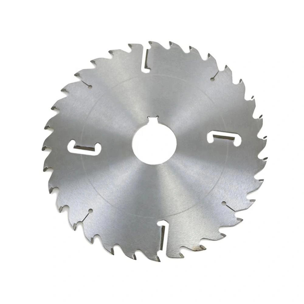
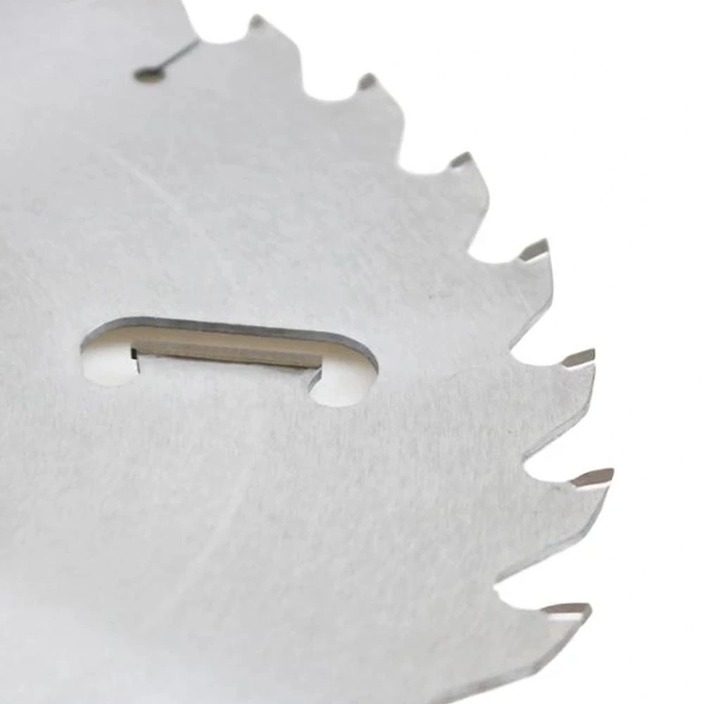
A replacement blade needs the right cutting width, plate thickness and center interface as well as the outside diameter. Match those details to the arbor and blade positions before choosing the configuration for your timber line.
Source a multi-rip saw blade with wipers as a complete cutting tool, rather than a diameter alone. This range brings together three outside diameters, two bore sizes, six tooth counts and three wiper quantities. The 4.0 mm kerf and 2.2 mm plate are stated separately so you can compare the proposed blade with your cutting layout. The table shows the available specification options; the final combination belongs on the quotation and blade drawing for your application.
| Specification | Options | Role in Your Order |
|---|---|---|
| Outside diameter | 254, 300 or 350 mm | Blade size for the machine and cutting position |
| Bore diameter | 40 or 60 mm | Center fit to the specified arbor |
| Peripheral tooth count | 40, 48, 60, 72, 80 or 96T | Cutting specification for the timber and feed conditions |
| Kerf | 4.0 mm | Width of the cut in the timber |
| Plate thickness | 2.2 mm | Body thickness within the blade and spacer arrangement |
| Body wiper quantity | Two, three or four | Number of wipers, separate from peripheral teeth |
| Keyway size option | 11 × 6 mm, width × depth | Keyway dimension; quantity and orientation specified separately |
These are independent options, rather than a catalogue of every possible combination. For example, a request for a 300 mm blade still needs its bore, tooth count, wiper structure and center pattern. A photograph identifies a design; the accepted configuration establishes the tool being purchased.
For an established line, send the current blade designation or drawing with the replacement quantity. For a new cutting arrangement, include the intended strip widths and the arbor assembly. This gives the inquiry a defined starting point without assuming that another machine's blade specification will transfer to yours.
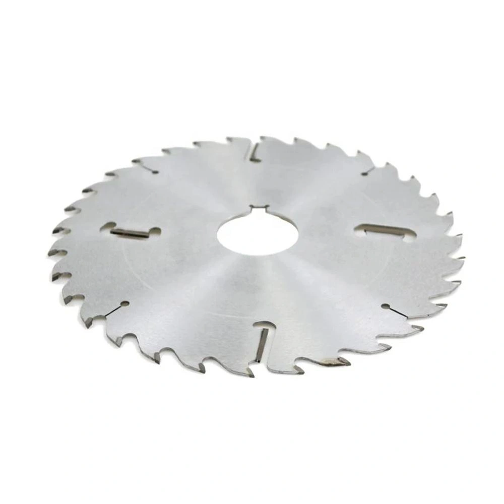
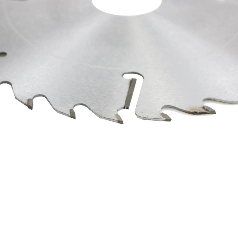
Wipers are separate from the peripheral teeth and form part of the blade's cutting structure.
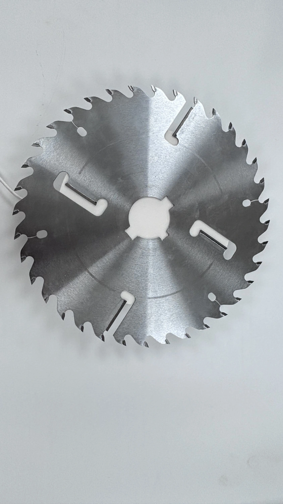
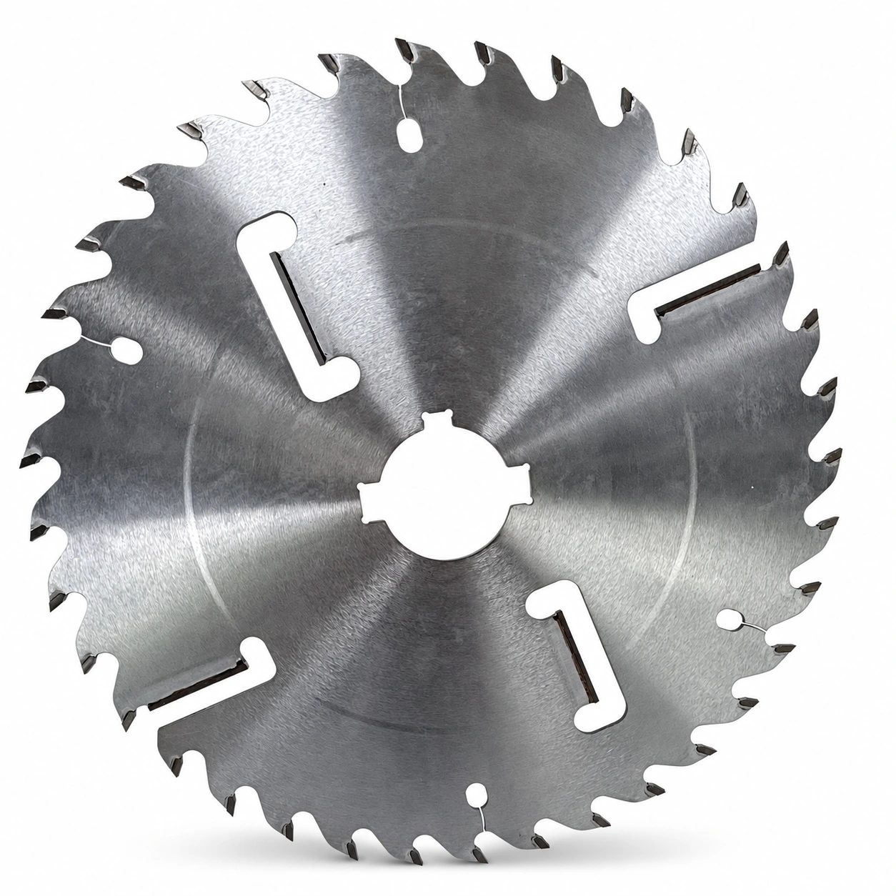
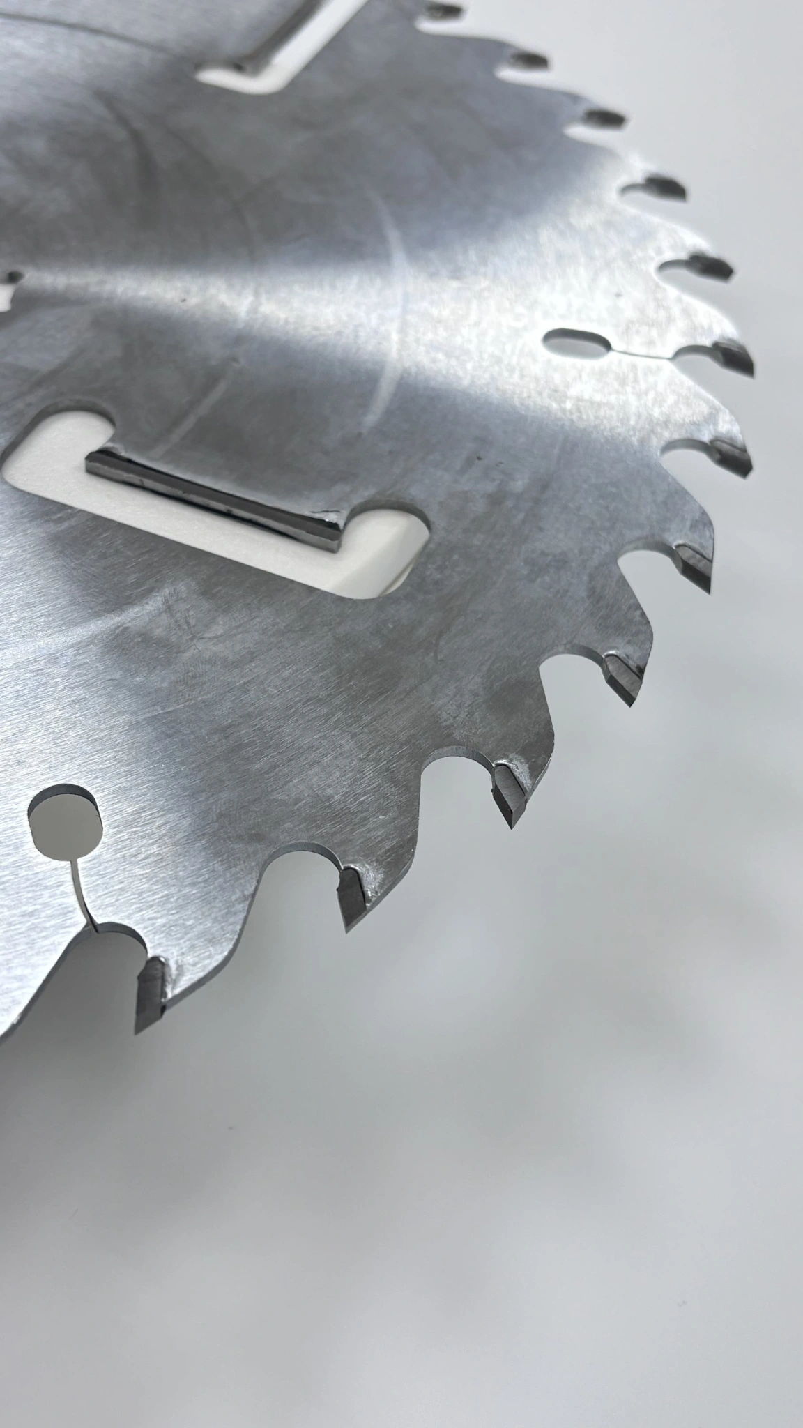
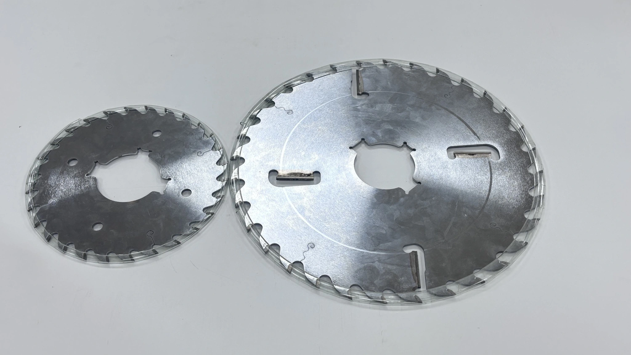
The pictured internal wipers sit within elongated, closed-ended openings in the blade body.
Other pictured wipers sit beside openings extending toward the rim, creating a distinct body layout.
A 4.0 mm kerf and 2.2 mm plate describe two different parts of the cutting arrangement.
Single, opposed and three-direction keyway examples show why the center pattern belongs in the specification.
Peripheral tooth count and body wiper quantity remain independent fields when describing the required blade.
Body wipers work within the cut, separately from the teeth around the blade's outside edge. Their general purpose is to maintain clearance between the plate and the timber. The product views show both internal body-slot wipers and peripheral open-slot wipers. When sourcing a replacement, use the actual structure as the reference: the word “wipers” and a quantity alone do not describe the complete blade face.
| Visible Structure | What Distinguishes It | Purchase Reference |
|---|---|---|
| Internal body-slot wiper | Wiper within an elongated opening with closed ends | Position, slot form and wiper arrangement on the blade drawing |
| Peripheral open-slot wiper | Wiper adjacent to an opening extending toward the rim | Relationship to the outer teeth and the specified body layout |
| Combined body layout | Internal and peripheral wiper positions on one design | Complete blade face, rather than an isolated detail |
“Rakers,” “scrapers” and “wipers” appear in industry descriptions of related structures. Specify the feature rather than relying on the name to establish interchangeability. A blade described as having four wipers can differ from another four-wiper blade in slot layout and center pattern. Keep those differences visible when comparing quotations; no finish, service-life or feed-rate advantage follows from wiper count alone.
A blade that matches the outside diameter can still have the wrong center interface. AXIMET's bore options are 40 and 60 mm, with an 11 × 6 mm keyway width-and-depth option. The pictured single-keyway, opposed-keyway and three-direction-keyway designs illustrate separate center arrangements. Select the required bore and keyway pattern together, using the arbor drawing or the accepted replacement specification as the mounting reference for your order.
| Center Detail | Required Definition |
|---|---|
| Bore | Exact 40 or 60 mm requirement and the specified mounting fit |
| Keyway dimension | Required width and depth, including whether the 11 × 6 mm option applies |
| Keyway pattern | Number of keyways and their orientation around the bore |
| Seating interface | Required flange contact and surrounding mounting components |
| Machine limits | Permitted blade size, rotation direction and operating-speed requirement |
The opposed-keyway and three-direction-keyway examples are different designs. Their dimensions are not established by their photographs, and the 11 × 6 mm option is not automatically assigned to either image. This matters when a group of similar-looking blades serves several machines: one line's replacement can have the right diameter and an incompatible center pattern.
Use actual metric dimensions in the order. A nominal inch description is useful for conversation, but 300 and 350 mm should remain 300 and 350 mm on the technical specification. The exact blade rating and the machine's approved setup govern operating speed.
The cutting arrangement connects the individual blade to the widths your line produces. In this range, the teeth establish a 4.0 mm kerf while the blade body is 2.2 mm thick. Those values serve different purposes within a multi-blade stack. Describe each blade position together with the spacers and clamping components so the quoted tools correspond to the required arrangement, particularly when replacing only part of an existing group.
| Arrangement Field | What Belongs in the Requirement |
|---|---|
| Cutting positions | Number of blades and their order on the arbor |
| Output | Required strip widths and allowance for subsequent machining |
| Blade dimensions | Diameter, kerf and plate thickness at each position |
| Spacers | Existing spacer arrangement or dimensioned assembly drawing |
| Side positions | Any different blade design specified at either end |
| Mounting group | Usable arbor length, seating and clamping arrangement |
A spacer dimension alone does not define finished strip width. Blade seating, cutting width and the positions of the cuts all contribute to the result. If a blade specification changes, the arrangement needs to account for that change before it becomes a production replacement.
A complete-group inquiry and an individual-spare inquiry therefore have different scopes. The first identifies the full working arrangement; the second identifies the position being restored. State which you need in the quantity schedule. This keeps a quotation for individual blades from being mistaken for a quotation covering a complete set for one machine.
The available peripheral tooth counts are 40, 48, 60, 72, 80 and 96T. Body wiper quantities are two, three or four. These choices belong to the cutting specification for your line; a higher count is not a universal upgrade. Start with the working blade for a replacement, or provide timber thickness, feed conditions and the required cut surface when purchasing for a new production task.
A rough-sizing operation before planing has a different purchasing target from strips with limited finishing allowance. The useful comparison is the output your next process can accept, together with the line's operating conditions. Tooth geometry and gullet form also matter; a tooth-count label by itself cannot establish a suitable feed rate or chip-handling capacity.
For an inquiry covering several timber sizes, distinguish the regular production requirement from an occasional job. Quote configurations against those tasks instead of assuming one blade will deliver the same result across all stock. Keep the peripheral tooth count and wiper quantity separate in each order line, including where a previous supplier used a combined notation.
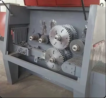
This collection addresses longitudinal timber ripping on industrial multi-rip or gang-rip equipment. Series application examples include birch, beech, American white oak, walnut, pine, white pine and larch. The relevant configuration depends on the actual timber, stock dimensions and production task. Use the applications below to describe the requirement; they do not imply that every diameter and wiper arrangement has been tested on every listed species.
For birch, beech, American white oak or walnut components, purchase against the incoming thickness and the strip dimensions required by the next operation. A rough-sizing allowance and a finished-edge requirement call for different acceptance targets. Tie the selected blade configuration to the species and production thickness, then judge the result by usable output after the agreed downstream machining allowance.
Pine, white pine and larch are series application examples for industrial ripping inquiries. Include the stock thickness, width pattern and resin conditions when selecting the cutting specification. For a line feeding a planer or another sizing process, the relevant output is a strip with the required machining allowance. Base the blade order on that operation, rather than a general softwood label alone.
When the same group repeatedly produces a defined width pattern, source the blades against that arrangement. The blade count, 4.0 mm kerf, 2.2 mm plate and spacer assembly belong together in the requirement. Identify any different side-position tools separately. This makes the order specific to the production pattern and gives individual replacement purchases a clear position reference.
For green, wet or variable-moisture stock, specify the measured moisture range as well as species, thickness and feeding conditions. Wipers alone do not establish wet-wood suitability. A configuration evaluated on dry boards needs an application review before use on materially different stock. Representative production timber provides the relevant basis for deciding whether the selected blade meets your required output.
A wiper-equipped multi-rip blade and a plain-body rip blade have different body structures. The comparison image makes that distinction visible: one blade has body wipers and the other has none visible. The image does not establish a matched cutting group or a performance ranking. For purchasing, retain the design specified for the task and compare alternatives against the same material, machine arrangement and output requirement.
| Purchase Question | Blade With Body Wipers | Plain-Body Blade |
|---|---|---|
| What is the visible structural difference? | Additional wiper features in the blade body | No visible body wiper features |
| What defines the replacement? | Peripheral teeth, wiper arrangement and mounting specification | Peripheral teeth, body design and mounting specification |
| Does the structure establish compatibility? | No; the complete interface and cutting arrangement still apply | No; the complete interface and cutting arrangement still apply |
| How should an alternative be assessed? | Against the production task and agreed acceptance criteria | Against the same task and criteria |
For an established wiper-blade application, an alternative without wipers represents a design change. Conversely, a plain-body blade specified for a particular position is not automatically unsuitable because it lacks them. Keep the job constant when assessing a change, so a different timber lot or machine arrangement does not obscure the comparison.
The broader TCT circular saw blade range covers other cutting requirements within a wider purchasing program.
A useful supply inquiry states how the blades will be used and replenished. You may need one replacement position, a complete group for a machine, or several configurations for distribution. These are different quantity schedules, even where they share the same diameter. Separate the technical configuration from the quantity required for each purpose so the quotation covers the actual buying requirement.
| Buying Requirement | How to Describe the Quantity |
|---|---|
| Individual replacement | Blade position or approved configuration, plus number of replacements |
| Complete working group | Quantity of each blade configuration in one group and number of groups |
| Production plus spares | Working requirement and spare quantity shown separately |
| Distributor assortment | Complete configuration and quantity for each stock line |
| Several production lines | Machine or line reference attached to each configuration |
For importers and distributors, the commercial unit is the configuration customers can actually use. A request for “300 mm multi-rip blades” is too broad when customers use different bores or keyway patterns. Base the assortment on identifiable machine requirements, with teeth and wipers included in each configuration. That also makes a price comparison meaningful across offers with similar product names.
Include the delivery destination and requested purchasing schedule with the quantity table. If you need particular identification, packaging or OEM presentation, describe the requirement in the inquiry for a configuration-specific offer. Those details belong in the agreed supply scope rather than being assumed from the product category.
For a larger purchasing program, separate technical approval from acceptance of the cutting result. Technical approval defines what is ordered: the blade, mounting interface and cutting arrangement. Production acceptance establishes whether that configuration meets the task under the agreed conditions. Keeping both tied to the same drawing or specification prevents a satisfactory sample from becoming an ambiguous reference for a different bulk order.
| Technical Approval | Production Acceptance |
|---|---|
| Diameter, bore and keyway pattern | Actual species, moisture range and stock thickness |
| Peripheral tooth count and body wiper arrangement | Required strip dimensions and acceptable variation |
| 4.0 mm kerf and 2.2 mm plate requirement | Surface condition and downstream machining allowance |
| Blade positions and assembly reference | Machine, feed conditions and extraction setup used |
| Configuration identifier and drawing revision | Evaluation record tied to that same configuration |
Evaluate an initial configuration on material representative of regular production. Useful observations include output dimensions, rubbing or burning, tear-out, feed behavior and the machine's available load indications. Agree on the acceptance target before comparing results. If temperature or other measurements form part of the evaluation, use a defined method under comparable conditions.
A production trial also reflects stock variation and machine setup. Resolve changes in the spacer arrangement, seating condition or material lot before assigning the result to the blade alone. Release a larger quantity against the tool configuration and acceptance requirement that were actually evaluated.
Purchase spares alongside the working requirement when a blade group is first specified. A spare must restore its intended position, including the center pattern, kerf, plate thickness and wiper structure. The right quantity depends on your maintenance plan: individual position spares and a complete replacement group serve different needs. Showing them separately makes the first order and later replenishment easier to define.
For several similar machines, use the line or assembly reference alongside the blade configuration. Two blades can share a diameter and peripheral tooth count while belonging to different keyed arbors. A distributor supplying those machines needs that distinction just as much as the production buyer does.
Serviced tools also need their own consideration. A reground blade and a new replacement may share an original catalogue description while having different current geometry or condition. Use the saw-service assessment and the resulting assembly requirement when deciding whether they belong together in a working group. Repeat purchase should follow the accepted replacement specification, including any revised requirement, rather than relying on an old photograph or diameter-only description.
Compare application fit, equipment compatibility and the supply configuration when preparing your purchasing requirement.
Specify the bore, keyways and complete mounting arrangement together. Keep different keyed designs identified separately when comparing drawings or replacement blades.
Record the peripheral tooth count and body-wiper count as separate fields. State the timber application and intended blade position when selecting the configuration.
Identify the blade positions and quantities for the cutting arrangement. Separate a complete replacement group from individual spare requirements in the quotation.
Body wipers maintain clearance between the blade plate and the timber within the cut. They are separate from the peripheral teeth. Their position and body-slot arrangement form part of the required blade design, alongside their quantity. Use the complete structure when specifying a replacement; the presence of wipers alone does not establish a guaranteed finish, feed rate or service life.
The terms overlap in industry use, but they do not identify one universal design. Internal body-slot wipers and peripheral open-slot wipers have visibly different arrangements. Specify the blade face and the intended structure on the order reference, with peripheral teeth and body wipers counted separately. Matching a supplier's terminology is less useful than matching the tool required by your machine and cutting task.
Diameter and bore are only part of the mounting specification. The keyway quantity, orientation, width and depth must also match the required center pattern. Include the seating and clamping arrangement, machine limits and blade position in the technical approval. The single, opposed and three-direction keyway examples represent distinct designs; similar product photographs do not establish that they fit the same arbor.
An existing spacer arrangement can remain the reference only when the replacement preserves the required cutting arrangement. Compare kerf, plate thickness, seating and blade positions with the accepted assembly. In this range, 4.0 mm is the cutting width and 2.2 mm is the plate thickness. A change to either dimension needs assessment against the required strip widths before it becomes a production replacement.
Submit wet-timber requirements with the actual species, measured moisture range, stock thickness and machine conditions. Wipers do not establish universal suitability for green or wet wood. Selection and acceptance need to address the proposed configuration on representative material. Keep that application distinct from a dry-timber order so a result from one production condition is not treated as evidence for another.
Reference the accepted blade specification, drawing revision and quantity for each configuration. Include the complete working group where applicable, plus separate spare quantities. A larger release should correspond to the configuration evaluated against your production requirements. State any identification, packing or OEM presentation requirement in the inquiry and agreed offer; do not assume it is included because a similar blade was supplied previously.
Send AXIMET a complete blade requirement or the reference needed to identify it. For a replacement, the existing drawing and clear views of the blade face and center pattern are useful starting points. For a new line, send the arbor assembly and intended cutting arrangement. Include:
State whether you are replacing an accepted configuration, evaluating an alternative or purchasing for a new setup. That gives the quotation a clear technical and commercial purpose. Keep the initial requirement with the eventual accepted configuration so the same information can support subsequent replenishment.