Form A Center Drills
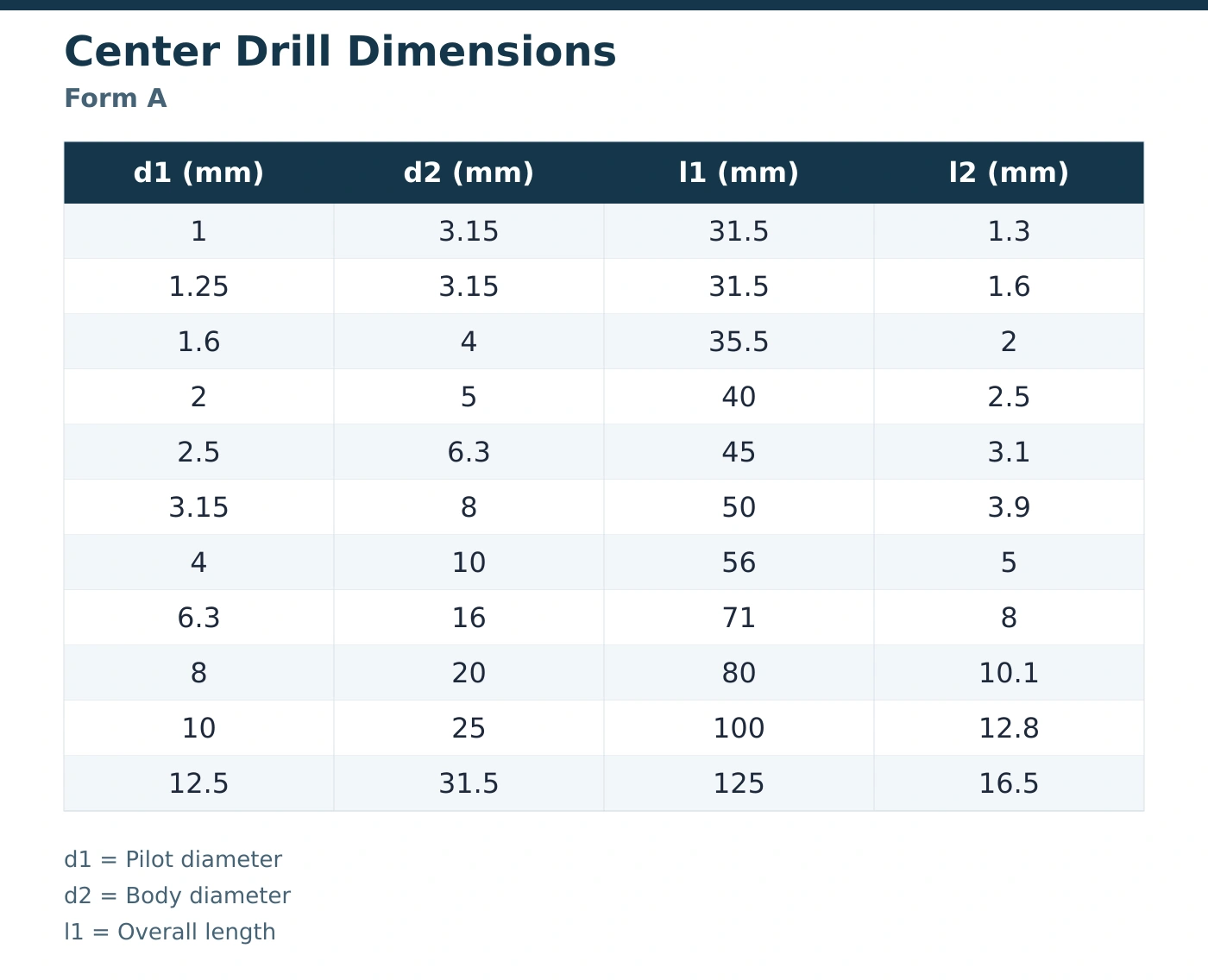
A conical supporting seat without an additional protective countersink. Eleven configurations cover pilot diameters from 1 to 12.5 mm.
Source HSS center drill bits for turning and grinding supply, with Form A and Form B configurations that let industrial buyers select the center-hole profile and dimensions required by their workpieces.
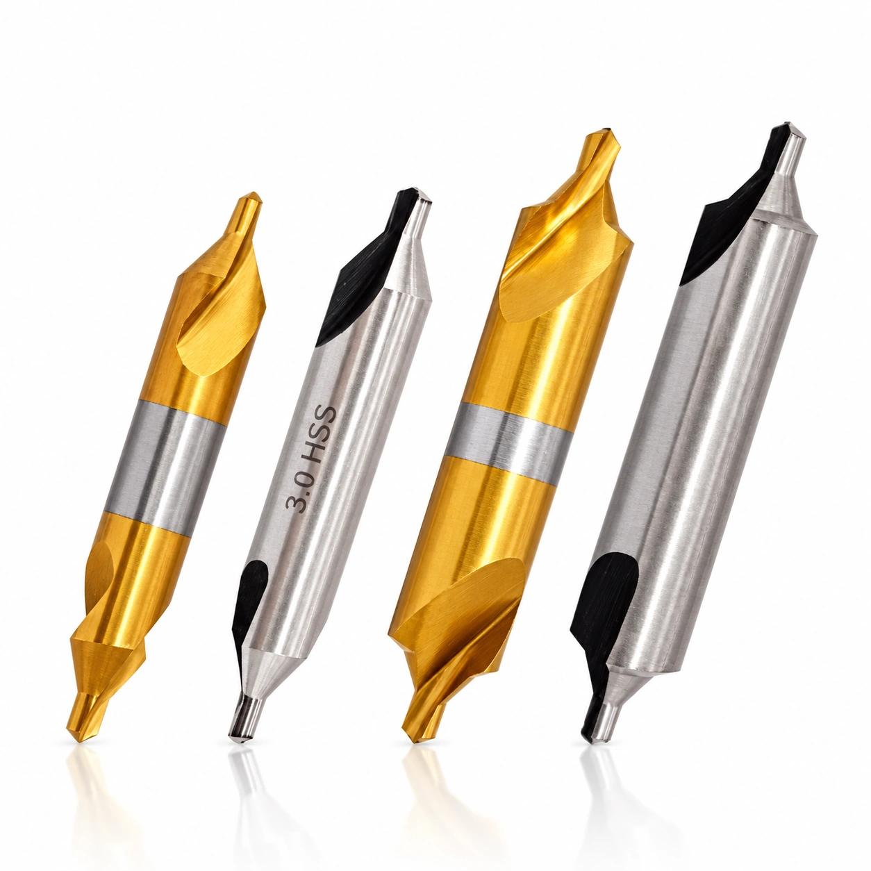
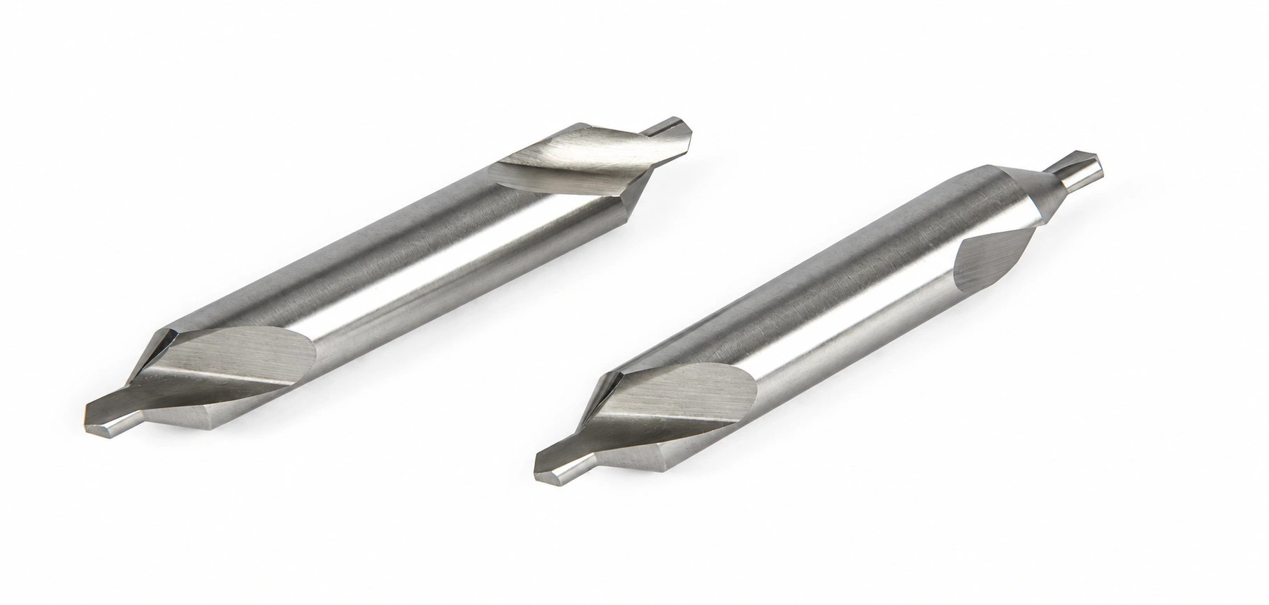
Select a center drill from the complete dimensional row rather than pilot diameter alone. The body, overall length and flute length affect holding and access, while the chosen form determines the center-hole entrance on the workpiece.
AXIMET offers HSS center drill bits for producing the pilot hole and supporting cone used by a machine center. This combined drill and countersink range is relevant to shafts and other components machined between centers. Begin with the center-hole form on your component drawing, then select a dimensional row for the tool and holder. The range below contains eleven Form A and eleven Form B configurations. Each form has its own body and length combinations; a shared pilot diameter does not identify an interchangeable tool. For production replacements or distributor orders, specify the form alongside the dimensions.
A conical supporting seat without an additional protective countersink. Eleven configurations cover pilot diameters from 1 to 12.5 mm.
A supporting seat with an additional protective countersink at the entrance. Eleven configurations cover pilot diameters from 1 to 10 mm.
Use this center drill size chart to shortlist an exact configuration. All dimensions are in millimeters; each row describes one tool configuration within its named form.
| Pilot d1 (mm) | Body d2 (mm) | Overall l1 (mm) | Flute l2 (mm) |
|---|---|---|---|
| 1 | 3.15 | 31.5 | 1.3 |
| 1.25 | 3.15 | 31.5 | 1.6 |
| 1.6 | 4 | 35.5 | 2 |
| 2 | 5 | 40 | 2.5 |
| 2.5 | 6.3 | 45 | 3.1 |
| 3.15 | 8 | 50 | 3.9 |
| 4 | 10 | 56 | 5 |
| 6.3 | 16 | 71 | 8 |
| 8 | 20 | 80 | 10.1 |
| 10 | 25 | 100 | 12.8 |
| 12.5 | 31.5 | 125 | 16.5 |
| Pilot d1 (mm) | Body d2 (mm) | Overall l1 (mm) | Flute l2 (mm) |
|---|---|---|---|
| 1 | 4 | 35 | 1.3 |
| 1.25 | 5 | 40 | 1.6 |
| 1.6 | 6.3 | 45 | 2 |
| 2 | 8 | 50 | 2.5 |
| 2.5 | 10 | 56 | 3.1 |
| 3.15 | 11.2 | 60 | 3.9 |
| 4 | 14 | 67 | 5 |
| 5 | 18 | 75 | 6.3 |
| 6.3 | 20 | 80 | 8 |
| 8 | 25 | 100 | 10.1 |
| 10 | 31.5 | 125 | 12.8 |
The two 2 mm pilot tools illustrate why the full row matters. Form A combines a 5 mm body, 40 mm overall length and 2.5 mm flute length. Form B combines an 8 mm body, 50 mm overall length and the same 2.5 mm flute length. Changing form therefore changes both the center-hole entrance and the tool dimensions, even though the pilot specification stays at 2 mm.
There are also adjacent sizes with shared holding dimensions. The Form A 1 and 1.25 mm pilot tools both have a 3.15 mm body and 31.5 mm overall length, but their flute lengths are 1.3 and 1.6 mm respectively. They fit the same dimensional description only if the pilot and flute fields are omitted. Include all four fields when requesting a replacement or comparing offers.
For requirements outside these rows, send the required dimensions with your inquiry. A size listed under one form does not establish the same configuration under the other. For example, the table includes a 5 mm pilot Form B tool and a 12.5 mm pilot Form A tool; each belongs to its stated form and dimensional combination.
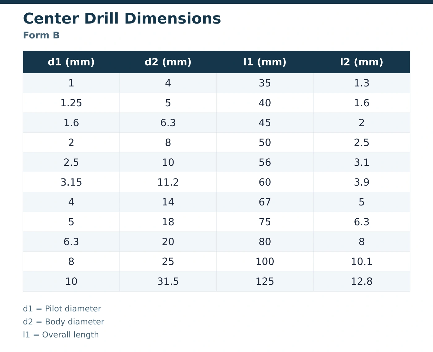
Produces the small hole beneath the supporting seat; pilot diameter remains a separate selection dimension.
Forms the seat that locates the workpiece against its machine center during machining.
Retains a plain center-hole entrance where the drawing does not require an additional protective countersink.
Adds a protective countersink outside the working cone when that center-hole profile is specified.
Provides the main holding diameter; body dimensions vary between forms even at matching pilot sizes.
Overall length and flute length describe different tool features and must remain separate in the specification.
The 60° centering angle describes the included angle of the supporting cone, while the small pilot has its own cutting point. For a purchase against a component drawing, include the required center-hole form and supporting angle together. This gives the technical buyer a clear geometry reference when selecting Form A or Form B center drills. Our drill point angle guide explains the separate cutting-point terminology.
Overall length affects tool access and holder position, so it belongs in an exact replacement specification alongside both diameters. Flute length is a different dimension: l2 in these center drill dimensions means flute length, rather than a specified center-hole depth. Use the component drawing to define the finished hole. This distinction is particularly useful when comparing a compact replacement with a tool described only by its pilot size.
This range consists of HSS center drills. For an application inquiry, provide the workpiece grade and hardness where known, together with the centering operation and existing tool specification. These details help frame a material-selection discussion without relying on the description “for metal.” If your purchase specification names a particular alloy grade or coating, state it explicitly. General-purpose holemaking tools are covered separately in our HSS and cobalt drill bits collection.
The most useful application description identifies the center hole's role in your process. A shaft turning operation, a component moving to grinding and a maintenance replacement may use similar-looking tools, yet have different drawing and purchasing requirements. Match the tool to the required support feature and the dimensions available at the machine.
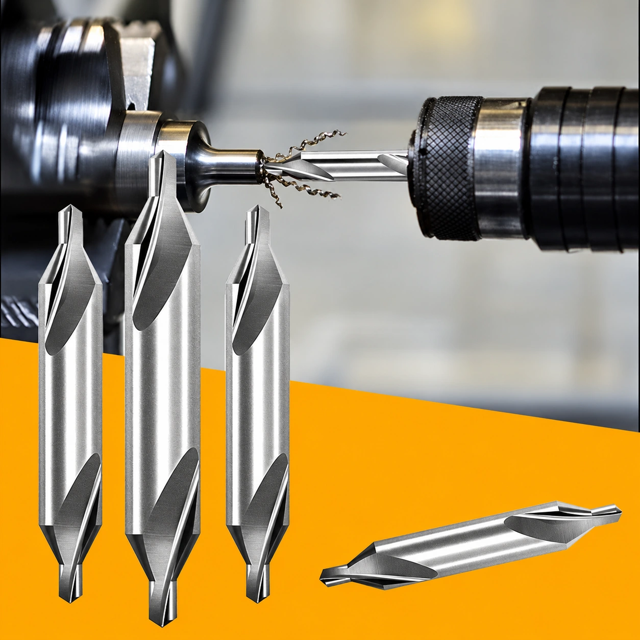
For steel shafts turned between centers, the center drill is selected to produce the support feature specified for the part. Form A suits a plain center-hole entrance; Form B is relevant where the drawing includes a protective countersink. Give purchasing the approved form and dimensional row along with the part reference. This keeps replacement orders tied to the required seat rather than a workshop description such as “small center drill.”
Where turned components subsequently undergo grinding between centers, the center-hole requirement carries through the machining route. Select the tool against the drawing used by the downstream operation, including any specified entrance profile. A Form B requirement should be carried into the purchase description rather than reduced to a pilot diameter. This gives turning and grinding teams the same reference when a replacement is ordered for the earlier operation.
Toolrooms handling several shaft sizes need replacements that match both the existing holder and the required workpiece feature. An intact reference tool, its drawing or an approved purchasing specification can identify the form, body and length. Where a pilot is worn or broken, the part drawing provides a better size reference than the remaining cutting tip. Separate routine replacements from a request to change the center-hole specification.
For a recurring production job, specify the center drill against the current component drawing and the accepted machine setup. Record the complete tool dimensions with the production requirement so the next order retains the same form and reach. If a process change introduces another workpiece grade or hardness, include that change in the inquiry. It deserves a technical review before purchasing treats the previous tool description as sufficient.
Choose the tool family by the feature being purchased for. A metalworking center drill produces a pilot and conical seat for support on a machine center. A spotting drill establishes a starting location for another drill. These requirements overlap in terminology but lead to different tool specifications.
| Tool Family | Purchasing Requirement | Key Selection Fields |
|---|---|---|
| Metalworking center drill | Center hole supporting a workpiece during machining | Center-hole form, supporting angle, pilot, body and lengths |
| Spotting drill | Starting location for a following drilling operation | Spot angle and diameter relative to the following tool |
| Spring-loaded self-centering drill | Guided pilot through hardware such as hinge holes | Guide sleeve, hardware opening and pilot size |
| Woodworking drill-and-countersink assembly | Pilot and recess for a wood screw | Screw size, pilot setting and countersink geometry |
For industrial supply orders, describe a metalworking requirement as a center drill or combined drill and countersink, with its form and metric dimensions. The supporting seat is the decisive feature when a workpiece will run between centers. If the requirement is only a starting location for a later drilling operation, assess the spotting tool specification instead.
Distributors serving both industrial and hardware customers can keep these families distinct in purchasing and resale descriptions. A hinge accessory described as “self-centering” does not replace a lathe center drill. Likewise, a drill-and-countersink assembly selected for a wood screw does not identify the support geometry required by a metal shaft. Naming the final task alongside the tool dimensions makes the inquiry easier to interpret.
Start with the way you will use or resell the tools. A production buyer may need one recurring dimensional row; an industrial distributor may need several pilot diameters in separate quantities. A proposed mixed set needs an itemized contents list. These are different purchasing configurations, even when they draw on the same Form A and Form B tables.
For a replacement order, quote the form first, followed by d1, d2, l1 and l2 in millimeters. A usable description is “HSS Form A; pilot 2 mm; body 5 mm; overall length 40 mm; flute length 2.5 mm,” followed by the required quantity. That identifies the configuration directly without relying on a supplier's number-size designation or a description based on appearance.
When comparing a proposed substitute, check changes against the holder and component requirement. A 2 mm pilot Form B tool has an 8 mm body and a 50 mm overall length, so the shared pilot is only one part of the comparison. A change in form also changes the entrance profile. Include any permissible alternatives as separate lines so a quotation can distinguish the exact match from a proposed change.
For recurring orders, retain the dimensional row and the relevant component drawing revision in your purchasing specification. If several machines use different center drills, state quantities by configuration rather than combining them under a single “center drill” line. This gives each replacement a defined destination and keeps a price comparison meaningful when orders contain both forms.
For distributor replenishment, allocate quantities to the pilot sizes and forms your customers actually request. Adjacent pilot sizes do not necessarily need equal quantities, and a familiar pilot does not establish the same body diameter across both forms. Use separate item lines for Form A and Form B so a buyer can identify the required center-hole entrance before choosing the size.
The Form A 2.5 mm pilot row, for example, has a 6.3 mm body and 45 mm overall length; Form B at the same pilot size has a 10 mm body and 56 mm overall length. They serve different form requirements and occupy different dimensional positions in an assortment. If you intend to carry both, the ordering and resale descriptions need to preserve that distinction.
Larger sizes also require their own quantity decision. Form A reaches a listed 12.5 mm pilot with a 31.5 mm body and 125 mm overall length. Form B reaches a listed 10 mm pilot with the same body and overall length but a different flute length and entrance form. Stock these against the configurations customers use, rather than treating a shared body diameter as a common size.
List the form, pilot, body, overall length, flute length and number of tools for each proposed set position. A piece count or the description “1–10 mm center drill set” leaves the actual contents unresolved. It does not state which intermediate sizes are included, whether the forms are mixed or how many tools of each size the buyer receives.
An assortment inquiry might list Form A rows at 1, 2 and 4 mm pilot diameters, each with its full dimensions and its own requested quantity. Another inquiry might use only Form B. These are examples of how to describe requested contents; the selection comes from your customer demand or production requirement. Add any duplicate sizes deliberately, especially when a set is intended to support repeated use of one common configuration.
For a mixed-form assortment, group the contents under clear Form A and Form B headings. If an outer description highlights only the pilot range, include the full itemized contents in the requested label information. This gives the person choosing a replacement the form and body dimensions as well as the small drill size.
Send the packaging format you require, the number of tools per pack and any grouping needed by size, form or assortment. For resale orders, provide the requested product wording, dimensional information, language, barcode data and artwork where relevant. These requirements belong with the item list so the quotation can address the proposed order as a whole.
If you need individual-size packs and mixed sets in the same inquiry, identify the quantities for each presentation separately. State whether the requested pack quantity means tools, packs or sets; those units affect the total order quantity. Any private-label request should include the intended label content and packaging requirements. The requested presentation and the quoted configuration should be reviewed together before the order is finalized.
Where you need technical matching, attach the center-hole drawing and identify the workpiece material, known hardness, operation and current tool. If you are qualifying a replacement after pilot breakage, include the failed tool's dimensions and the result observed. This provides a more useful starting point than increasing the pilot size, which would change the hole specified for the part.
State the requested quantity for the immediate order and, where useful, a separate forecast for later requirements. Add your delivery destination and required date so the quotation can address the actual purchasing schedule. If a sample order is part of your approval process, list its proposed configuration and quantity separately from the bulk requirement. Keep the accepted sample specification linked to the dimensions used for the subsequent order.
Compare application fit, equipment compatibility and the supply configuration when preparing your purchasing requirement.
Choose Form A or Form B for the required center-hole profile. Keep that choice attached to the full dimensional configuration when requesting replacements.
Compare pilot diameter, body diameter, overall length and flute length separately. Check holding and access against the intended turning or grinding setup.
List the selected configurations and quantities for production use or distribution. Specify any assortment contents directly rather than relying on a group photograph.
A metalworking center drill produces a pilot hole and conical seat for supporting a workpiece on a machine center. For a procurement requirement, identify the part's center-hole form and select the corresponding tool dimensions. Turning and grinding operations can depend on that support feature through more than one process stage. The relevant purchase is therefore a defined form and size, rather than a general drill for starting any hole.
A number-size designation needs its own dimensional reference before it can be compared with a metric tool. Use the pilot, body and lengths from the original specification, then compare them with the relevant Form A or Form B row. Rounded conversions can conceal a dimensional difference. If your purchasing system uses a number size, retain it alongside the verified dimensions and units so both descriptions identify the same required tool.
No. The 60° centering angle refers to the included angle of the supporting cone; the small pilot's cutting point is a separate feature. An inquiry describing only a “60° drill” does not identify the required center-hole form or dimensions. Include Form A or Form B, the dimensional row and the component drawing where the supporting geometry is specified. If your requirement cites a DIN designation, include its exact reference and drawing revision.
This AXIMET range is HSS. A specification calling for cobalt-alloy HSS or solid carbide represents a different material requirement and needs a product-specific response. Include the workpiece grade, hardness and application when discussing material selection. If your approved specification names an alloy grade or coating, quote that requirement directly. Tool color alone does not establish a material grade or coating, and it is not a reliable basis for a replacement order.
A larger pilot changes the center hole, so review it against the component drawing before requesting that substitution. For a replacement inquiry, send the existing form and dimensions, workpiece information and the circumstances of the failure. Alignment, holding and cutting conditions can affect a small pilot independently of the nominal tool size. Where your approval process includes samples, assess the proposed replacement in the intended setup against your finished-hole requirements.
Send a line for each form and dimensional row, with the requested quantity and unit. For a proposed set, itemize every included tool and identify any duplicate sizes. Add the requested packaging format, label information, delivery destination and required date. Application details and a center-hole drawing are useful where you need help matching a tool. This makes the inquiry specific enough to address the tool selection and the commercial configuration together.
Send AXIMET your Form A or Form B requirements with pilot diameter, body diameter, overall length, flute length and quantity for every line. Attach the center-hole drawing when ordering against a defined component feature or reviewing an alternative to an existing tool.
For distributor or assortment inquiries, include the proposed contents, quantities by configuration and requested packing units. Add any label or private-label requirements as part of the inquiry, together with the destination and required date. If you have both an immediate order and an anticipated replenishment requirement, show them separately so the quotation addresses the current purchase clearly.
Send Your Center Drill Requirements to AXIMET