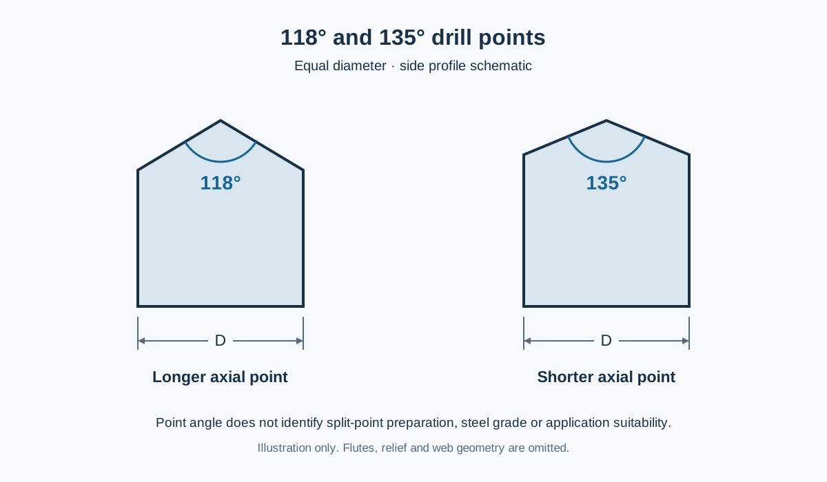
At equal diameter, a 135° drill point is flatter and shorter than a 118° point. Neither angle identifies a split point, cobalt grade or suitable workpiece. Choose the complete drill geometry for the hole, material and machine; use the angle to describe one part of that specification.
118° vs 135° Drill Point: the Differences That Matter
The point angle is the nominal included angle between the two main cutting lips as projected in the specified side view, with the projection plane parallel to the drill axis and the cutting lips. It describes the overall tip shape. At the same diameter, a larger included angle produces a flatter profile.
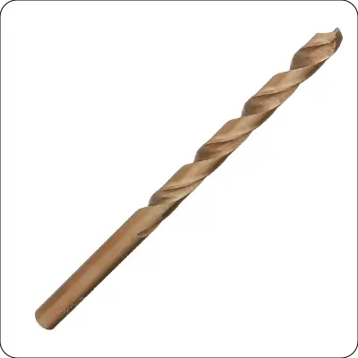
That difference is easy to see in a dimensioned drawing. It is harder to judge from an oblique product photograph, where perspective, reflections and the split-point grind can obscure the cutting lips. Use the specified angle for purchasing and inspection rather than measuring a catalogue thumbnail.
| Feature | 118° Point | 135° Point | Purchasing Implication |
|---|---|---|---|
| Overall profile at equal diameter | More pointed | Flatter | Compare drawings at the same scale |
| Ideal axial point length | Longer | Shorter | Allow for the point when specifying hole depth |
| Split-point preparation | May be present | May be present | State point preparation separately |
| Drill material and coating | Separate specifications | Separate specifications | An angle does not identify HSS, M35, M42 or coating |
| Application suitability | Depends on the complete drill | Depends on the complete drill | Use the selected product's material guidance |
| Flat-bottom capability | Does not produce a flat bottom | Does not produce a flat bottom | Specify another hole-making method when required |
A flatter point is therefore a geometric difference, not a universal quality ranking. A poorly matched 135° drill does not become suitable merely because another 135° product performs well in the same industry.
Separate Point Angle from Split-Point Geometry
The main point angle describes the outer tip profile. Split-point grinding changes the central web and chisel-edge region. Those are different features, so a specification such as “135° split point” contains two useful pieces of information.
The distinction is supported by actual manufacturer examples. Dormer Pramet's HSS range includes the A002 with a 118° split point and the A108 with a 135° split point. A buyer cannot reliably translate “118°” into “conventional point” or assume that every 135° drill has a split point.
Split-point preparation can help a suitable drill start centrally and reduce thrust compared with the corresponding conventional design. The benefit still depends on the rest of the tool and the setup. It does not make a long overhanging drill rigid, correct a poorly held workpiece or guarantee hole location on every entry surface.
For a repeat order, retain the complete product code or approved drawing. For an alternative supplier, state both the included angle and the point preparation. If the original tool uses a particular web-thinning form, an end-view photograph or drawing helps communicate what “same point” means.
Why the Same Angle Can Give Different Drilling Results
Two drills can share a nominal point angle while differing in cutting-lip shape, web thickness, relief, helix, flute space, length and edge preparation. They may also use different substrates or coatings. Treating them as interchangeable conceals the features that may explain their different behaviour.
A straight, short drill and a longer drill of the same diameter do not present the same stiffness and access trade-off. A geometry intended for one chip-forming material may not clear chips equally well in another. A different shank or holding arrangement can introduce another change before the point reaches the workpiece.
When a buyer reports that “135° worked better,” the useful next question is what else changed. Was the replacement shorter? Was it split-point ground? Did the workpiece batch, coolant supply or machine change? Without that context, an otherwise successful trial can produce an unreliable purchasing rule.
Keep angle comparisons narrow: compare complete tools under a stated application, then record the complete successful specification. This gives a distributor a repeatable item description and gives the workshop a replacement that is more likely to match the approved sample.
Choose the Drill for the Workpiece and Hole
Start with the part rather than an angle chart. Identify the material grade and condition, hole diameter, required depth and acceptable hole quality. Describe angled entries, curved surfaces, interrupted exits or cross holes because those features can change the selection problem.
Then consider the machine and holding arrangement. A drill intended for a rigid production setup may not be the appropriate choice for a portable operation, even if both tools share an angle. Access restrictions can also force additional length that affects stability and chip evacuation.
This sequence follows the application-based approach in Sandvik Coromant's drilling guidance: assess the hole, component and machine together. The practical purchasing question is which finished drill suits those conditions, not which angle wins in isolation.
For example, a buyer replacing a successful stainless-steel drilling tool should retain the material recommendation and full geometry in the comparison. Selecting any drill marked 135° would discard important information. Likewise, an existing 118° tool should not be rejected solely because a competing catalogue presents a different angle as premium.
For alloy differences, compare the separate M35 cobalt drill and M42 cobalt drill specifications. The alloy designation does not determine the point angle, and the point angle does not verify the alloy.
Blind-Hole Depth: Tip Depth Is Not Full-Diameter Depth
A twist drill begins with a point. Its tip reaches farther into a blind hole than the circular shoulder where the hole first reaches full diameter. Confusing those positions can leave a hole shallower than the drawing requires or carry the tip into material that must remain intact.
Read the drawing's depth definition before comparing tools. It may specify the cylindrical full-diameter portion, the deepest point, a usable thread depth or a remaining wall thickness. Those requirements are related but are not the same dimension.
At the same diameter, a 135° point generally needs less axial point allowance than a 118° point. That can matter when space beneath a blind hole is limited. It does not eliminate the allowance, and it does not create a flat-bottom hole.
Use the actual tool drawing for production depth planning. A split point, a special lip profile, wear or a regrind may make the real geometry differ from a simple cone. If the hole will be tapped, also account for the following tool's requirements rather than treating the drill-tip position as usable thread depth.
An Ideal Point-Length Calculation
An ideal conical point gives a useful illustration of the difference. If the diameter is D and the included point angle is θ, the axial point length h is:
h = D ÷ [2 × tan(θ ÷ 2)]
For an ideal 10 mm diameter point, that gives approximately 3.00 mm at 118° and 2.07 mm at 135°. The shorter point is a consequence of geometry; these numbers are calculated examples, not AXIMET product dimensions.
Imagine a drawing requiring a defined cylindrical depth. The ideal tip would travel beyond that depth by the corresponding point length. The comparison explains why two equal-diameter drills can produce different tip depths when their full-diameter shoulders finish at the same position.
This illustration is not a CNC program, a tapping-depth allowance or permission to approach a thin wall by the calculated margin. Set production travel from the actual tool geometry, component drawing and qualified process. When reviewing a supplier's point-angle drawing, check that diameter, included angle and axial point length are identified and that any example dimensions are distinguished from the dimensions of the offered drill.
Through Holes, Sheet and Irregular Entries
Through-hole work also involves more than the point appearing at the far surface. The point can break through before the full diameter has passed through the material. A depth or clearance assessment must distinguish initial breakthrough from completion of the cylindrical hole.
In thin material, the entry and exit conditions occupy a large part of the operation. Workholding, backing, the intended drill geometry and the required edge condition can matter as much as the headline angle. Do not replace application guidance with a rule that all sheet needs one angle.
Curved or angled entry surfaces create a different starting condition from a flat face perpendicular to the drill axis. A split-point label does not remove that difference. Ask for a tool and process intended for the actual entry rather than assuming that better centring on a flat surface proves suitability everywhere.
When access is restricted, include the space behind the workpiece in the enquiry. The selected diameter and point profile, required breakthrough and machine arrangement all affect the clearance needed. A shorter point can reduce one geometric contribution without solving every access problem.
Diagnose Poor Holes Before Changing the Point Angle
A wandering start, oversized hole or damaged cutting edge may prompt an angle change. First establish whether the problem follows the tool geometry, the setup or the workpiece. Changing several features together can hide the cause and make the next replacement difficult to specify.
| Observed Problem | Questions to Investigate | Why Angle Alone Is Insufficient |
|---|---|---|
| Start is off location | Entry shape, holding, overhang, point preparation | Centring involves the central geometry and setup |
| Hole is oversize or inconsistent | Lip symmetry, holder condition, alignment, runout | Unequal cutting action can alter the result |
| Chips pack in the flutes | Depth, chip form, flute design, coolant arrangement | Point angle does not define chip-carrying capacity |
| Reground tool behaves differently | Relief, lip equality, web thinning, remaining length | Matching one nominal angle may miss other changes |
| Blind-hole depth is wrong | Drawing definition, actual point length, following operation | Tip depth and cylindrical depth differ |
These are investigation prompts, not a diagnosis from a photograph. Record the actual symptoms and application before requesting a replacement. Where the tool is damaged or the operation is unstable, resolve the cause with the tool and machine guidance rather than continuing simply to compare angles.
Resharpening Must Preserve More Than the Included Angle
A drill can be reground to the stated angle and still lose the behaviour of the original point. The cutting lips need an appropriate relationship to each other, and relief, chisel edge and any thinning must remain suitable for the design.
For production tools, give a qualified regrinding service the original tool specification and the required preparation. State whether the drill has a split point and whether the application relies on a particular geometry. The remaining length and condition also determine whether continued reconditioning is worthwhile.
Keep new and reground samples identifiable during evaluation. A mixed box makes it difficult to tell whether a reported change comes from the nominal product or its service history. Do not compare an unknown regrind with a new drill and attribute the entire difference to 118° versus 135°.
If a buyer approves a reground tool for a repeat operation, record that approval separately from the new-tool sample. This preserves a useful distinction for purchasing, workshop instructions and future supplier comparisons without assuming that every regrind will reproduce the same result.
Compare Samples with a Clear Acceptance Question
Decide what the trial must establish before comparing purchase prices. The requirement may be reliable starting, specified hole size, acceptable breakthrough condition, full-diameter depth or useful tool life in a particular workpiece. Those outcomes need an agreed definition.
Use representative material and the intended machine. Keep the hole requirement, holding arrangement and coolant conditions consistent, and document each tool's complete specification. If the tools need different operating recommendations, record them rather than forcing an unsuitable common setting for the sake of an apparently equal test.
Measure the result that matters to the part. An attractive chip or a lower apparent drilling effort does not by itself prove that the hole meets its size, location or depth requirement. Separate rejected holes, tool changes and reconditioning when considering the cost of a repeat order.
A useful trial report names the tool code, workpiece, machine, conditions and acceptance result. It should not collapse that information into “135° passed.” The fuller record makes a later substitution easier to assess and prevents a successful sample from being replaced by a superficially similar drill.
Specify a Repeatable Bulk Order
For an enquiry, send the drill diameter, flute length, overall length, shank, material grade, finish or coating, included angle and point preparation. Add the workpiece and hole requirement when asking for application advice. A clear photograph of the original point can supplement the specification without replacing it.
Where a distributor sells several drill families, keep angle, point form and alloy in separate catalogue fields. This lets customers filter accurately and avoids a product title that implies every cobalt drill has the same geometry. Use the same separation in a purchase order and sample approval record.
For a replacement, identify what must stay unchanged and which alternatives may be considered. A different length or point preparation may be acceptable after a trial, but it should not enter a repeat order silently. Refer to the approved sample or drawing revision when the geometry is important to the application.
AXIMET enquiries can begin with the HSS drill range and the required size list. Include the complete point specification so a quotation addresses the tool you need rather than treating 118° or 135° as a complete description.
Frequently Asked Questions
Is a 135° Drill Point Always Better Than 118°?
No. At equal diameter, 135° gives a flatter, shorter point, but that geometric difference does not rank complete drills. The tool still needs the right substrate, cutting geometry, length and application range. Compare finished tools in the actual workpiece and machine, using a defined hole requirement. A successful 135° product does not prove that every tool with that angle will give the same result.
Does Every 135° Drill Have a Split Point?
No. The included angle and split-point preparation are separate specifications. The angle describes the overall profile; splitting modifies the central web and chisel-edge region. Manufacturers also offer 118° split-point drills, so the relationship works neither way. For ordering, write both fields or use a complete product code. If replacing a particular preparation, provide a drawing or a clear end view as supporting information.
Does Point Angle Identify M35 or M42 Cobalt Steel?
No. M35 and M42 identify material grades, while 118° and 135° describe geometry. A photograph of the tip cannot establish the alloy, and a cobalt label does not establish the included angle. Keep grade, coating, dimensions and point preparation separate when comparing offers. For a repeat purchase, match those fields to the approved product rather than assuming one feature proves the rest. Retain the exact approved tool code where available.
How Does Point Angle Affect Blind-Hole Depth?
The drill tip extends beyond the full-diameter cylindrical portion of the hole. At equal diameter, a 135° point has a smaller ideal axial allowance than 118°. Read whether the component drawing specifies cylindrical depth, tip depth or usable thread depth, then use the actual tool drawing and process requirements. The ideal cone formula explains the difference, but it does not replace production depth planning.
Does a 135° Drill Produce a Flat-Bottom Hole?
No. A flatter point remains a point and leaves a corresponding bottom profile. If a component needs a genuinely flat bottom, define that geometry and select an appropriate tool or finishing operation. Do not substitute a point-angle change for the required bottom shape. The same distinction matters when checking clearance beneath a blind hole or planning the depth available for a following operation.
Should I Change the Angle When a Drill Wanders?
Investigate the entry surface, workholding, tool overhang, holder condition and point preparation first. Wandering does not identify the included angle as the sole cause. An unequal regrind or an unsuitable starting condition can also change the result. Describe the actual workpiece and symptom when requesting advice, then compare an appropriate replacement under controlled conditions instead of changing the angle and several other features without a record.
Conclusion
Use 118° and 135° to describe the drill point, then choose the complete tool for the job. Keep split-point preparation, alloy and coating separate, allow for the point in depth planning, and preserve the approved geometry in repeat orders. For an AXIMET enquiry, send the size list together with the workpiece, hole requirement and complete point specification.