GE GEH GEI GEJ Series · R084
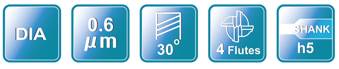

Build a graphite end mill assortment around the diameters and lengths your customers actually use. AXIMET’s GE, GEH, GEI and GEJ catalogue models bring four-flute options together in one range, with individual dimensions for specification and repeat ordering.
Graphite workpieces vary in size, feature detail and tool access. Start with the cutting diameter and feature drawing, then check flute length, overall length and shank diameter against the machine and holder. Different length variants are not interchangeable simply because their nominal diameters match.
The graphite end mill range contains 17 listed model records. All listed models have four flutes. The GE, GEH, GEI and GEJ prefixes identify catalogue entries with different dimensions; consult the relevant model row rather than assuming a particular length is available in every diameter.
The catalogue drawing identifies cutter diameter, flute length, effective length, overall length and shank diameter. Use those fields together to prepare a quotation list. When matching a customer’s existing tool, compare the complete geometry and dimensions, not just the printed model code or overall length.
For example, GE0304Z and GEH0304Z have the same listed cutting diameter but different flute and effective lengths. Compare the complete model rows and the corresponding drawing when assessing access; effective length is not the same as flute length.
Cutting diameter. Match the diameter to the feature width and access around the workpiece. A cutter for an open graphite surface is selected differently from one that must enter a narrow channel.
Flute length. Compare the fluted cutting section with the planned axial engagement. More exposed cutting length is not automatically useful for every feature.
Effective length. Where listed, compare the dimension identified on the series drawing with the required feature access. Do not treat it as flute length or assume that the holder has sufficient clearance without checking the assembled tool.
Overall length and holder fit. A longer tool may reach farther outside the holder, but its usable projection depends on clamping depth and assembly clearance. Confirm shank diameter, holder and machine space before ordering.
Workpiece and operation. Give the graphite application and the operation when requesting a recommendation. Include part geometry, finish expectations and any drawing-controlled requirements so the quoted model can be compared to the intended task.
Graphite electrodes can include open surfaces, shoulders, narrow steps and deeper recessed details. Use the end profile and toolpath to determine the desired feature, then select the appropriate size and access. For a deep or narrow groove, compare the feature with a long-reach tool instead of assuming an extended overall length alone provides the same neck clearance. A curved contour may call for a graphite ball-nose end mill; check the programmed profile and catalogue dimensions before selecting it.
Graphite dust management is part of machine setup. Use collection and handling measures appropriate for the workpiece, equipment and workshop, following the machine and material supplier’s guidance.
For a sample or repeat order, identify the dimensions you intend to inspect, such as cutter diameter, shank diameter, flute count and overall length, against the selected model’s drawing. Keep the approved model and drawing revision with the purchase record. State any documentation, label or packaging requirements in the quotation request so they can be reviewed for your order.
Compare the listed GE, GEH, GEI and GEJ sizes with the cutter length and holder requirements of your graphite work.
| Type No. | Diameter (D, mm) | Flute length (Lc, mm) | Effective length (L1, mm) | Overall length (L, mm) | Shank Dia (d, mm) | Flutes (F) |
|---|---|---|---|---|---|---|
| GE0304Z | D3 | 9 | 20 | L60 | 3 | 4 |
| GE0404A | D4 | 12 | 25 | L60 | 4 | 4 |
| GE0604 | D6 | 25 | 35 | L75 | 6 | 4 |
| GE0804 | D8 | 25 | 35 | L75 | 8 | 4 |
| GE1004 | D10 | 35 | 50 | L110 | 10 | 4 |
| GE1204 | D12 | 50 | 65 | L110 | 12 | 4 |
| GE1604 | D16 | 60 | 80 | L150 | 16 | 4 |
| GEH0304Z | D3 | 12 | 30 | L75 | 3 | 4 |
| GEH0404A | D4 | 12 | 30 | L75 | 4 | 4 |
| GEI0304Z | D3 | 9 | 30 | L100 | 3 | 4 |
| GEI0404A | D4 | 12 | 30 | L100 | 4 | 4 |
| GEI0604 | D6 | 25 | 40 | L100 | 6 | 4 |
| GEI0804 | D8 | 30 | 40 | L100 | 8 | 4 |
| GEJ0604 | D6 | 25 | 40 | L150 | 6 | 4 |
| GEJ0804 | D8 | 50 | 70 | L150 | 8 | 4 |
| GEJ1004 | D10 | 50 | 70 | L150 | 10 | 4 |
| GEJ1204 | D12 | 50 | 70 | L150 | 12 | 4 |
The photographs below show production equipment and workshop operations used as manufacturing-reference material for carbide tooling enquiries. Process requirements are confirmed for the selected model and order.
Enclosed CNC tool-grinding equipment shown on the workshop floor.
Multi-tank cleaning equipment shown in the workshop.
A row of enclosed CNC grinding machines viewed from the workshop aisle.
Enclosed tool-grinding equipment with an adjacent operator area.
Tool-grinding equipment with a robotic handling enclosure.
Enclosed grinding and robotic-handling equipment shown from another workshop position.
CNC grinding machines arranged along a workshop aisle.
Enclosed tool-coating equipment shown in the production area.
Vacuum-chamber equipment shown in the coating area.
An operator works at an enclosed laser-marking station.
Machine workstations shown in a tool-finishing area.
An operator stands beside tool honing and polishing equipment.
An operator stands beside enclosed edge-honing and polishing equipment.
Enclosed wet-blasting equipment shown in the surface-finishing area.
A second workshop view of enclosed wet-blasting equipment.
The photographs below show inspection and measurement equipment used when discussing drawing dimensions and order requirements. The inspection scope is confirmed for the selected order.
Operators work at optical inspection stations.
An operator positions a cutting tool at a profile-measuring station.
Optical measurement workstations shown in the inspection area.
A balancing instrument with a protective enclosure.
A tool presetting station with an optical measuring arm and display.
An optical tool presetter with a measurement display.
Operators inspect tools at camera-based optical workstations.
An operator positions a tool in an enclosed measuring machine.
It is selected for milling graphite workpieces, including features on graphite electrodes. The appropriate diameter, length and tool profile depend on the part drawing and machining setup.
The GE, GEH, GEI and GEJ models listed in this catalogue group are four-flute tools. Check the individual model row for its dimensions.
No single tool length fits every cavity. Check the feature depth, tool projection and holder clearance. A dedicated long-reach geometry may be needed for restricted access.
Compare the cutting diameter, flute length, overall length and shank diameter on the GE model row with the electrode feature and holder. For a recessed feature, check whether another geometry is needed for access.
Coating requirements should be checked against the selected model and order specification. Include the requested coating in your inquiry; do not assume the same finish applies across every model.
Send the model, quantity per size, graphite application, machine and holder information, together with any required drawing, label or packaging details.
Send your GE, GEH, GEI or GEJ model list with quantities, cutter diameters and required lengths. Include the graphite application and holder details so we can prepare your quotation.