SDS Plus
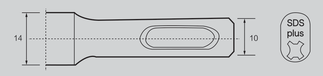
10 mm shank diameter. Select the holder specified for your exact hammer. Use its manufacturer-approved, non-rotating chiselling mode.
Match the blade width and approach to the tile-removal job—not just the hammer connection.
AXIMET SDS tile removal chisels combine an integral tile-lifting blade with an SDS Plus or SDS Max connection. Compare seven complete configurations in 40, 50 and 75 mm blade widths, including the individually specified 15° bent forms. Match the connection first, then compare the blade approach and clearance for your floor or wall application. For a wholesale assortment, select each complete row and add its quantity and packaging requirements to one enquiry.



Choose the hammer connection before the blade. SDS Plus and SDS Max are different holder systems and are not directly interchangeable.
10 mm shank diameter. Select the holder specified for your exact hammer. Use its manufacturer-approved, non-rotating chiselling mode.
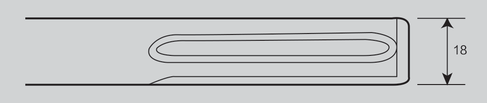
18 mm shank diameter. Select the holder specified for your exact hammer. Use its manufacturer-approved, non-rotating chiselling mode.
A hexagonal body does not make an SDS Plus chisel a hex-shank hammer accessory. The 250 × 40 mm hexagonal-body bent option below still uses the SDS Plus connection.
SDS Plus and SDS Max identify different holder systems. The listed shank diameters help distinguish the families, but a diameter by itself is not a complete compatibility check. Use the machine’s specified connection and permitted operating mode. Send the exact machine model when the intended equipment is part of the enquiry; a description such as “electric hammer” is too broad to identify a holder.
A drill-only tool cannot be made suitable for chiselling simply by choosing an SDS-labelled accessory. The hammer must provide the prescribed non-rotating chiselling operation. Follow its instructions for accessory insertion, retention and use. This page does not assign a universal power rating, impact-energy threshold or cross-brand approval to the seven configurations.
When supplying a mixed customer base, separate SDS Plus and SDS Max in the catalogue, pick list and carton description. Keep the interface visible even when two tools share a 75 mm edge. Avoid describing the SDS Plus hexagonal-body version as “hex shank”: its body outline and its connection are different parts of the product description.
Each row is one available configuration. L is overall length and W is blade width; all dimensions are in mm. Select a row to add its complete specification to your message.
Showing all 7 configurationsShowing 5 SDS Plus configurationsShowing 2 SDS Max configurations
| Product / series form | Connection | Body | Profile | Length L | Width W | Bend | Enquiry |
|---|---|---|---|---|---|---|---|
| SDS Plus | Round | Bent wide blade | 250 | 40 | 15° | |
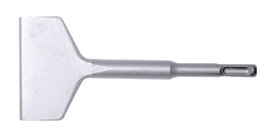 | SDS Plus | Round | Bent wide blade | 165 | 75 | 15° | |
| SDS Plus | Round | Bent wide blade | 250 | 75 | 15° | |
| SDS Plus | Round | Tile blade | 260 | 40 | Tile blade | |
 | SDS Plus | Hexagonal | Bent wide blade | 250 | 40 | 15° | |
| SDS Max | — | Tile blade | 300 | 50 | Tile blade | |
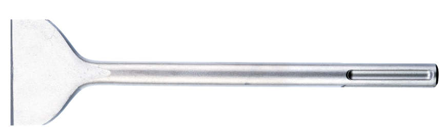 | SDS Max | — | Bent wide blade | 300 | 75 | 15° |
The five 15° entries are specified bent configurations. The 260 × 40 mm SDS Plus and 300 × 50 mm SDS Max tile forms have no angle listed; “Tile blade” is not a zero-degree claim. SDS Max body shape is not separately specified in this size table.
Series images identify a working form, not an individual photograph of every length. Choose the dimensions from the row, not from the image scale. On smaller screens, scroll the table horizontally; the page itself stays within the screen.
A narrower edge needs less entry space; a wider edge needs room to engage across the blade. Overall length describes the complete tool, rather than exposed reach after insertion. Compare the space for the hammer-and-chisel assembly as well as the distance to the tile bed.
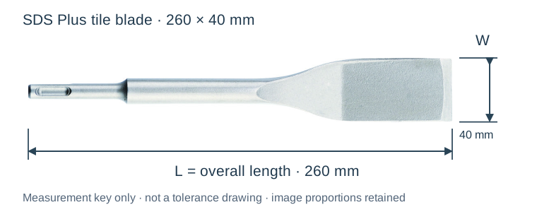
The 15° bend changes the blade approach relative to the shaft; it is not a fixed operating-angle instruction. The 260 × 40 mm SDS Plus and 300 × 50 mm SDS Max tile forms have no angle assigned.
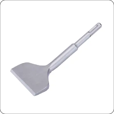
The two 250 × 40 mm, 15° bent SDS Plus options differ in body form. Include “round body” or “hexagonal body” in the item description. Both retain the SDS Plus connection; a hexagonal body does not fit a hex-hammer holder by implication.

The 250 × 40 mm round-body, 15° bent configuration is a narrower bent-blade choice. Consider it when the customer needs a defined entry edge around tile joints, boundaries or restricted access. Its selection difference is the combination of a 40 mm edge with a bent approach; it should not be substituted automatically for another tool that merely has the same width.
The 165 × 75 mm round-body, 15° bent configuration combines a wider blade with the shortest overall length in this range. Compare it where a broad edge is wanted but the available working space makes a longer accessory inconvenient. Overall length alone does not establish the clearance for a complete hammer-and-chisel assembly, so include the machine body and the surrounding surface in the comparison.
The 250 × 75 mm round-body, 15° bent configuration retains the same stated blade width and bend while providing a different overall length. Choose between these two 75 mm SDS Plus forms by reach and access, rather than describing one as a higher-performance version. They remain separate order lines, even when a distributor sells them under the same tile-removal family.
The 260 × 40 mm round-body tile form is a separate profile. Its length is 260 mm, and the table does not assign it a 15° bend. A buyer replacing a 250 × 40 mm bent chisel should compare the head and approach rather than assuming the extra ten millimetres are the only difference.
The 250 × 40 mm hexagonal-body, 15° bent configuration serves buyers who require that body form while retaining an SDS Plus holder connection. State “hexagonal body” in the order description. Calling it simply a hex chisel can cause confusion with accessories designed for a hex-hammer tool holder.
The 300 × 50 mm SDS Max tile form and the 300 × 75 mm SDS Max, 15° bent form share an overall length but differ in both width and working profile. Compare the 50 mm tile form where its narrower edge and approach suit the removal task. Compare the 75 mm bent version where wider contact and that offset profile are wanted. The 50 mm tool is ordered as the tile form; the 75 mm version carries the specified 15° bend. Keep that profile distinction in the item description when requesting both.
Start from an accessible edge or damaged area. Compare entry space, blade approach and the bedding layer before choosing width. Assess the retained substrate before the next preparation step.
Account for corners, fittings, wall construction and machine clearance. State whether neighbouring tiles or finishes must remain. A wide edge suited to an open floor may be awkward beside a wall fitting.
Choose the entry edge and overall length for the available working position. Include the hammer body in the clearance check. Distinguish a need for narrower contact from a need for greater reach.
The tile bond, bedding material and retained surface affect the choice of tool and approach. Explain whether work begins at an exposed edge, within a damaged tile or beside a retained finish. A photograph of that boundary is more useful than naming the tile alone.
After lifting, assess adhesive, mortar ridges or loose render before choosing the next profile. A tile chisel does not replace a polisher, a joint-cleaning blade or every surface scraper. No damage-free removal result is promised.
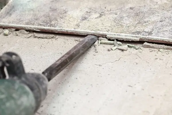
Choose the next tool by its working edge and the condition of the remaining surface.
Integral blade for lifting at the tile-to-bed interface. Match the holder, entry profile, width and length to the available access.
Narrow straight working edge for a defined chipping task. Select for the local contact required rather than the offset tile-lifting approach.
Broad straight working edge for suitable exposed surface removal. Consider the remaining bed or residue after tiles have been lifted.
Separate blade-and-holder assembly with a replaceable blade and fasteners. Specify the interface and replacement blade when spare parts are required.
Compare SDS chisel types · Tile, mortar and render selection guide · How to use an SDS chisel
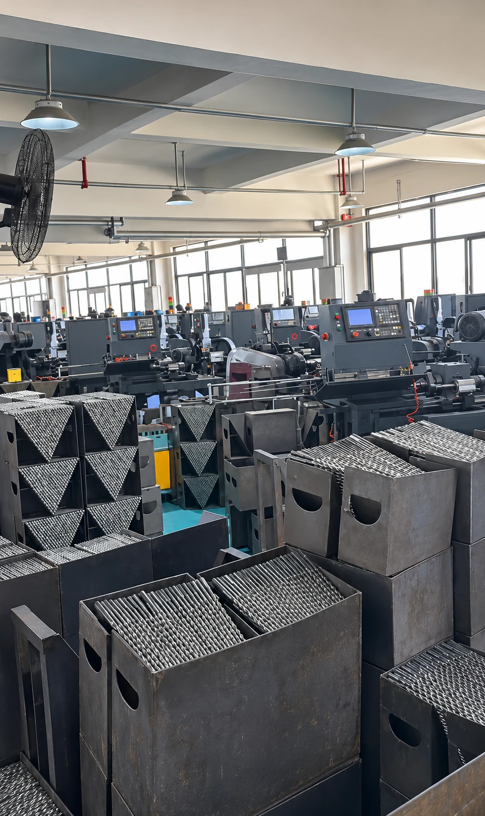
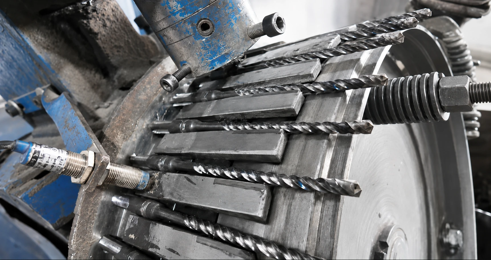
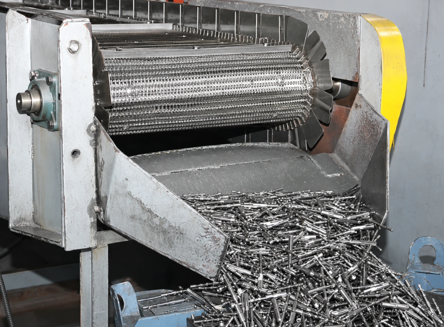
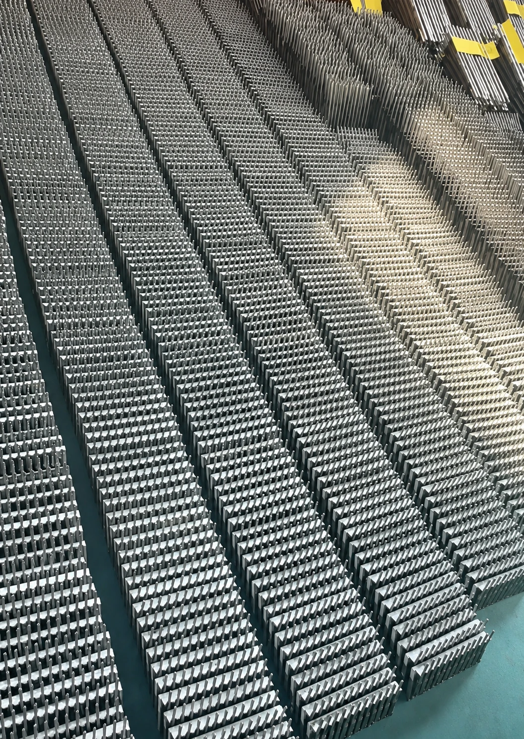
AXIMET manufactures SDS and masonry accessories through forging, heat treatment, machining and finishing processes within the same production system. Workholding and finishing routes follow the tool geometry, from chisel bodies and working ends to fluted drilling accessories.
The Tile Chisel gallery and seven-row specification table provide product-specific evidence. This factory capability tour shows the shared equipment, processing stages and batch handling behind the wider accessory range.
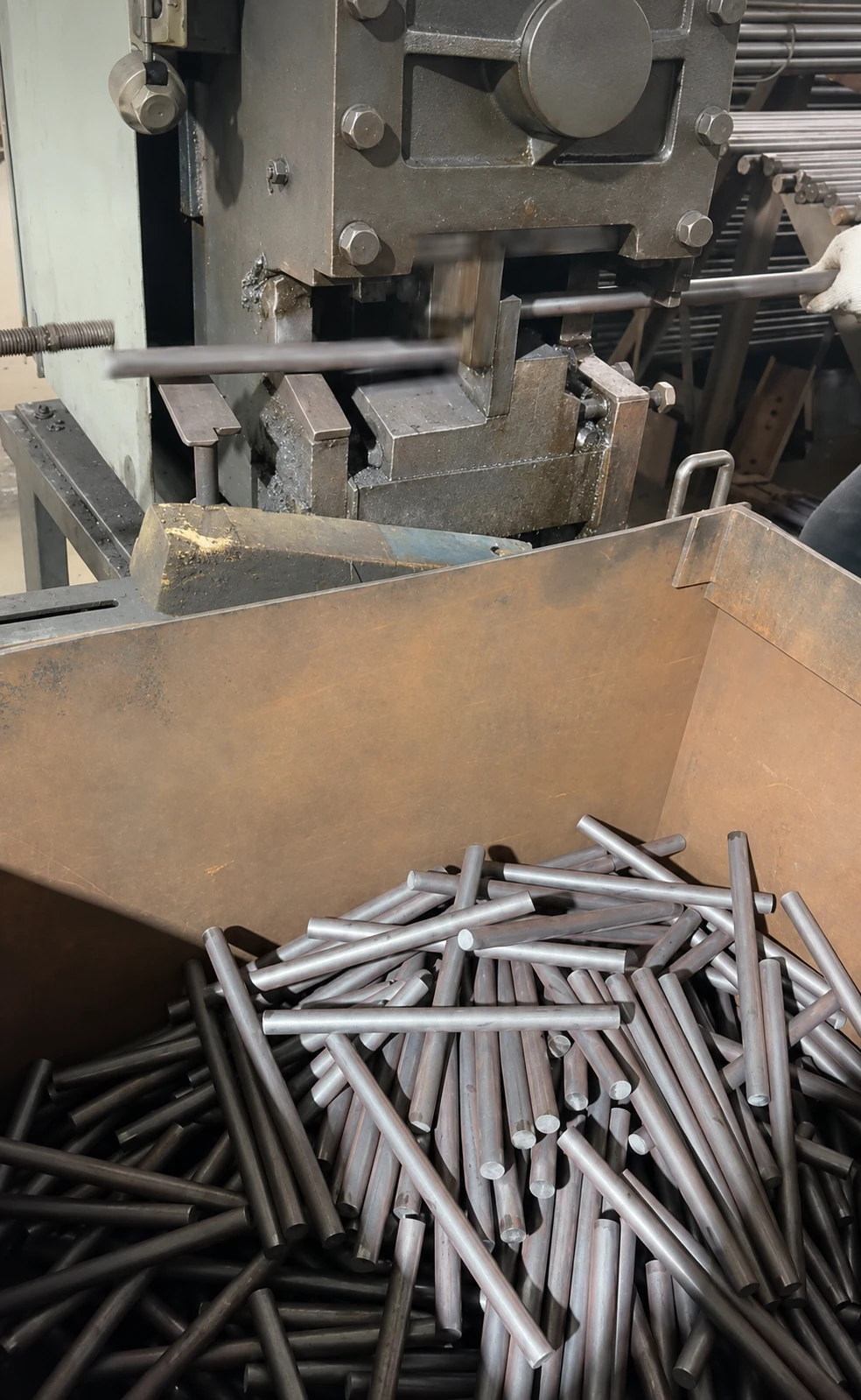
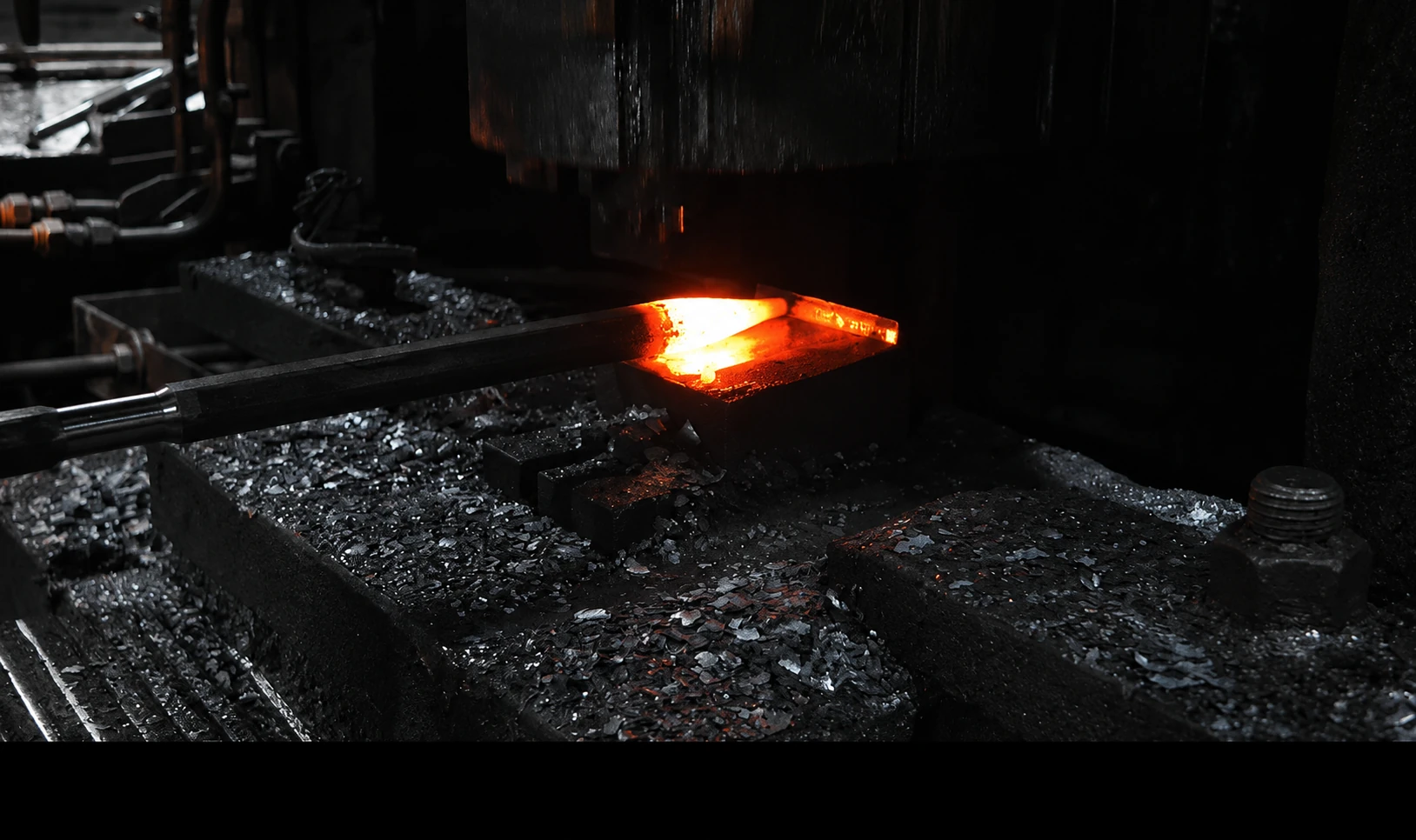
Bar preparation, die-side positioning and hot forging connect stock preparation with the subsequent machining route.
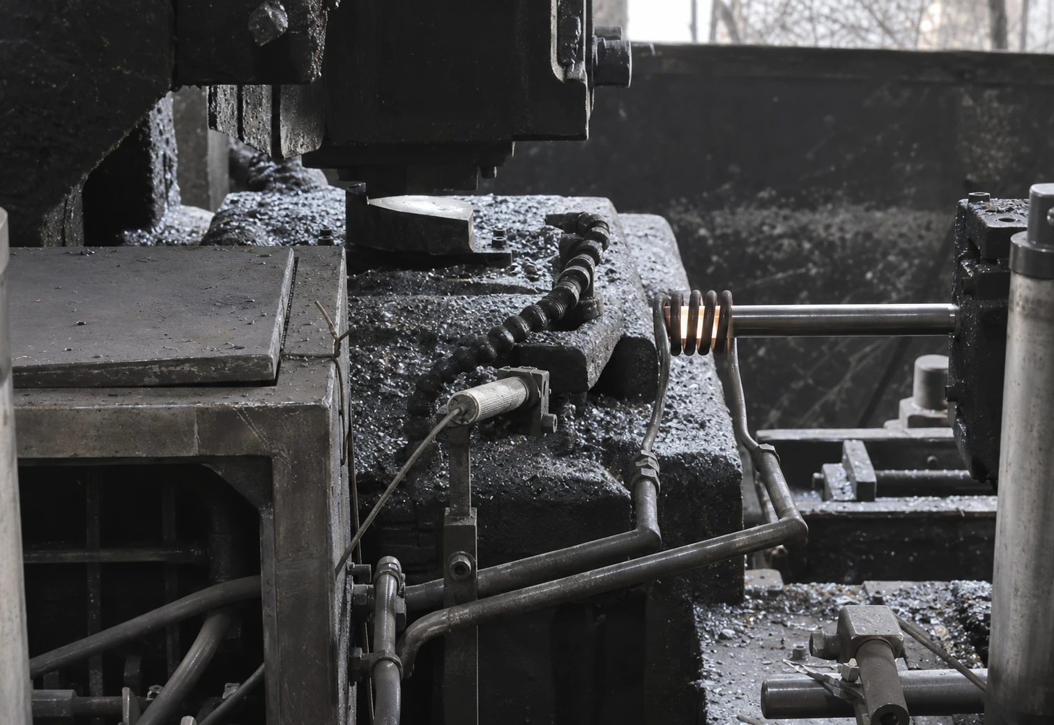
AXIMET’s heat-treatment workflow uses furnace and localized heating equipment across tool production. These views show furnace loading and induction heating around chisel shanks and drill rods. Material and process requirements remain attached to the ordered configuration.
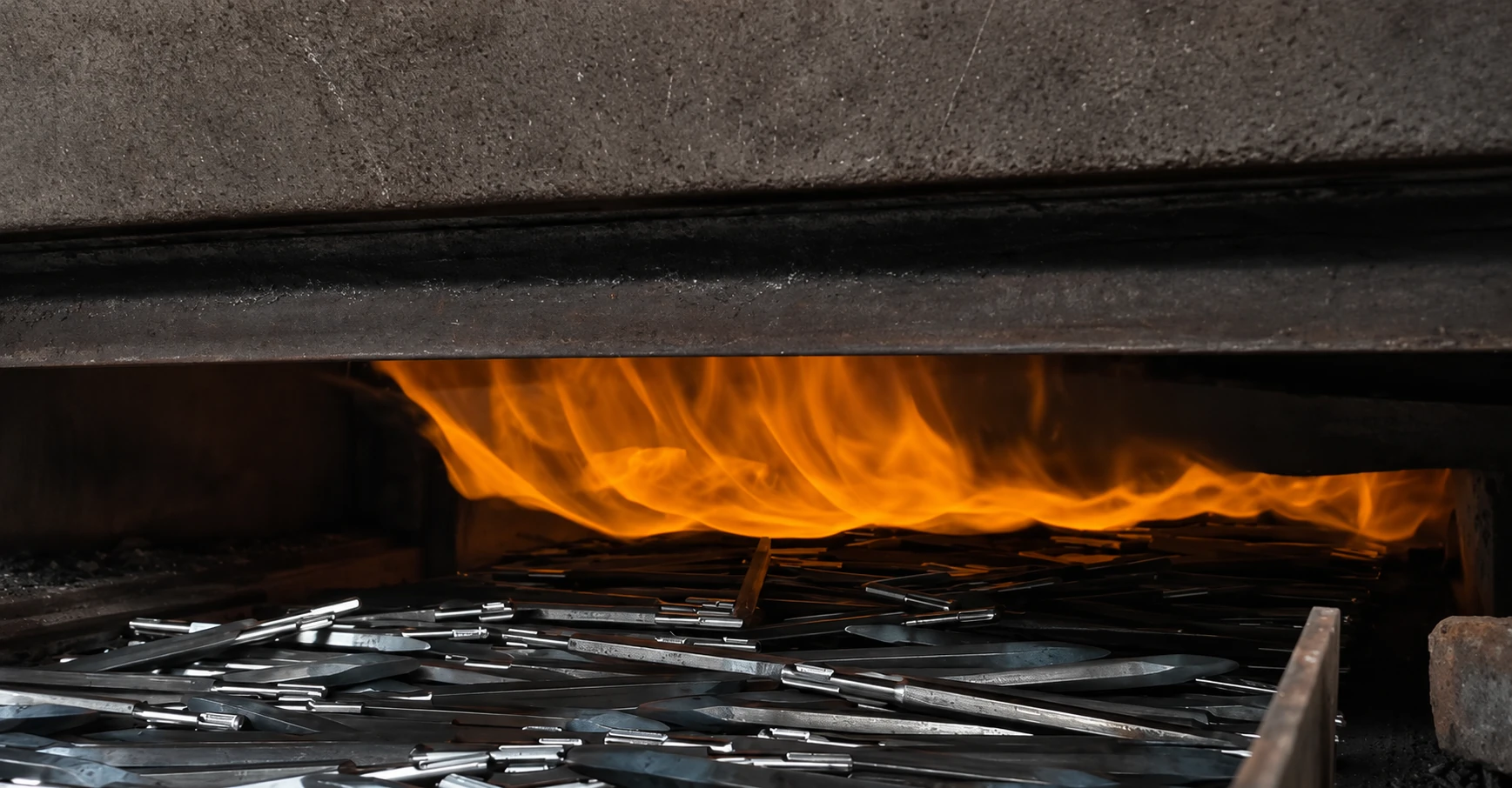
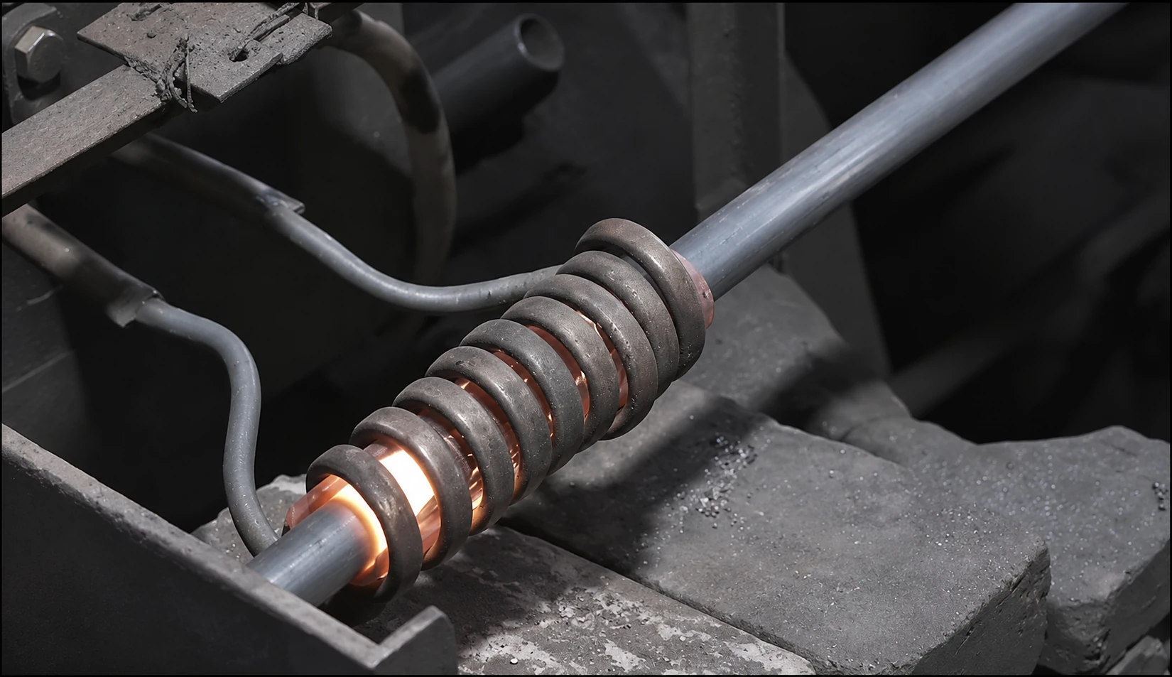
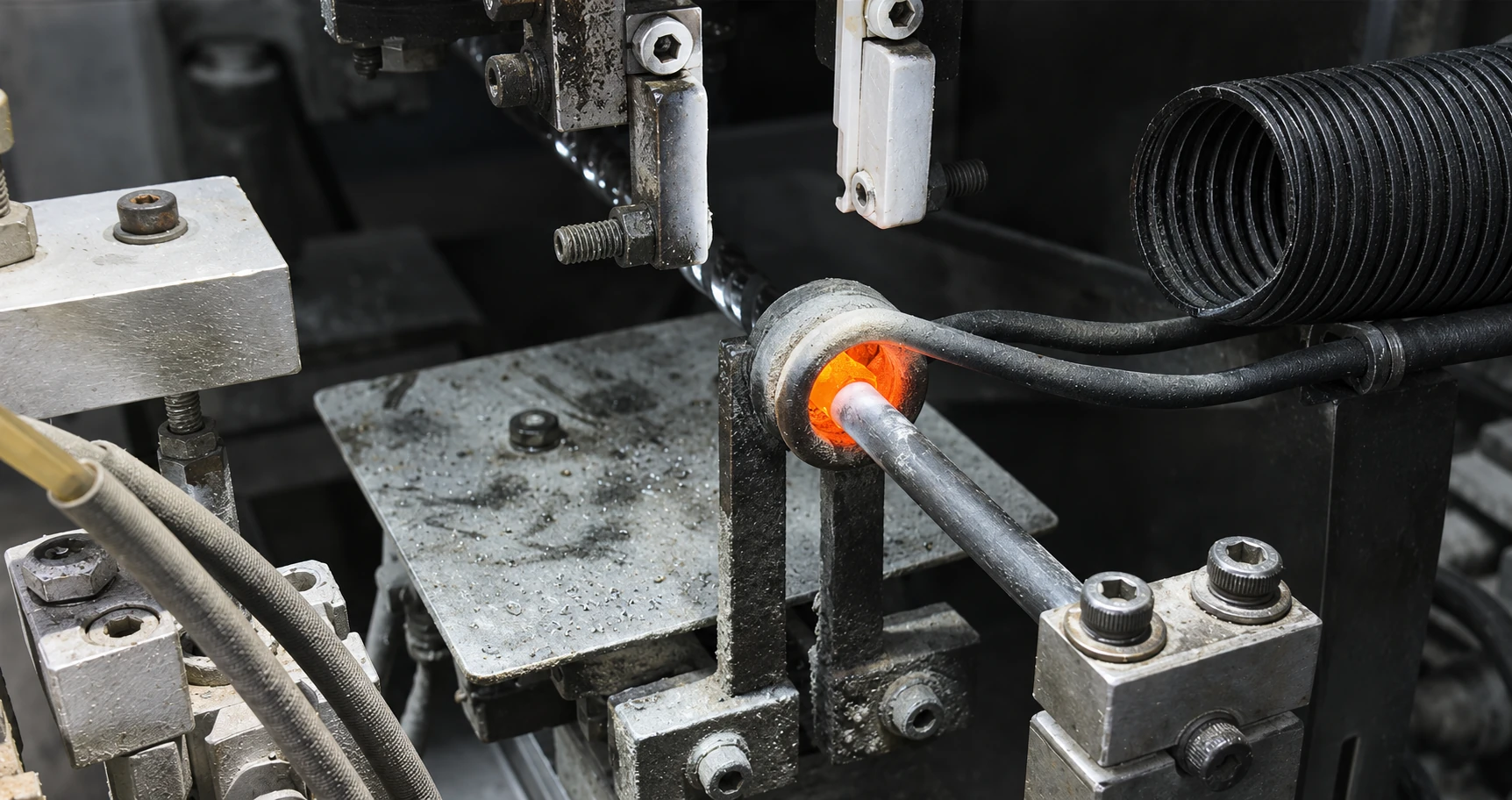
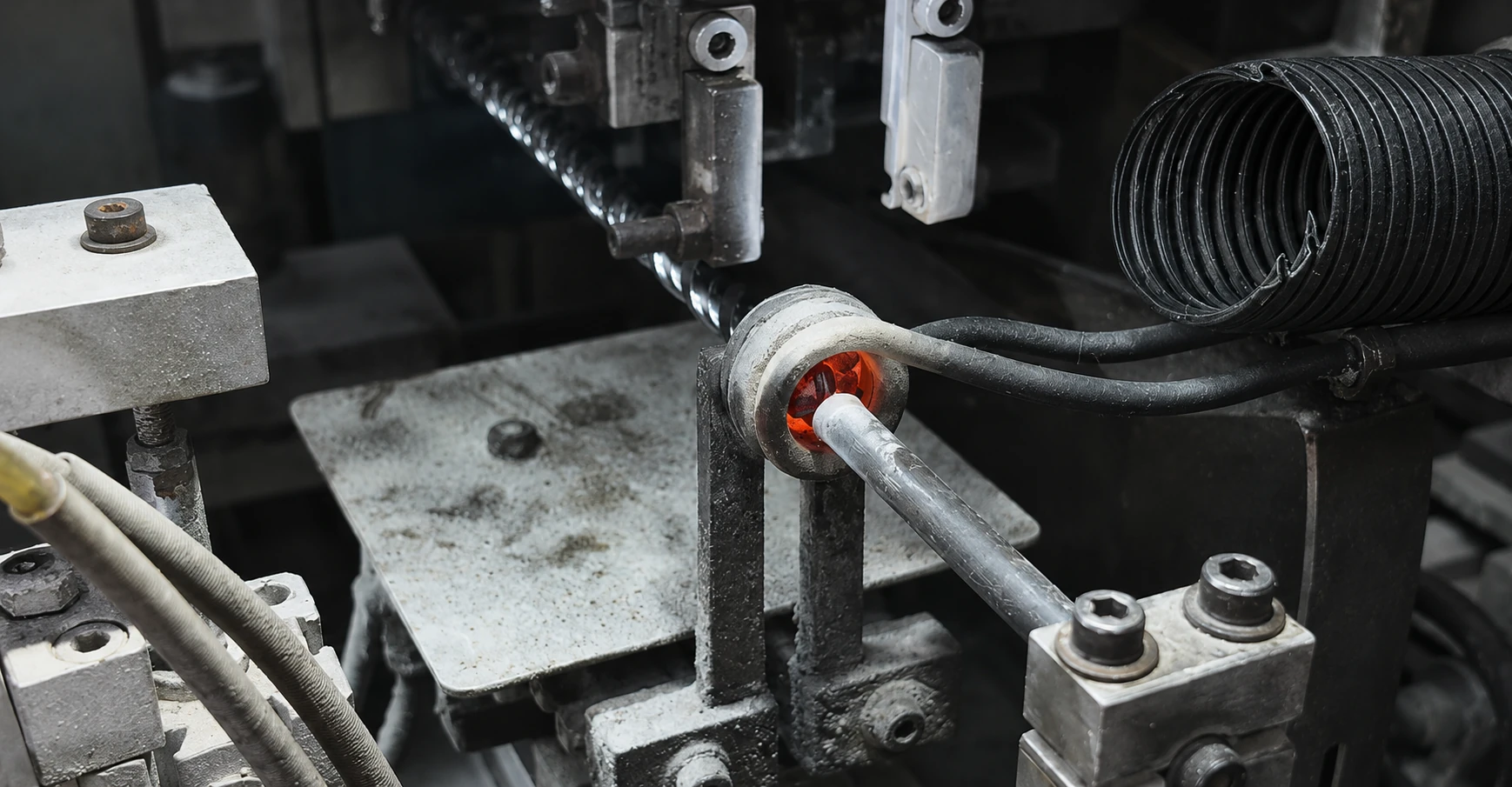
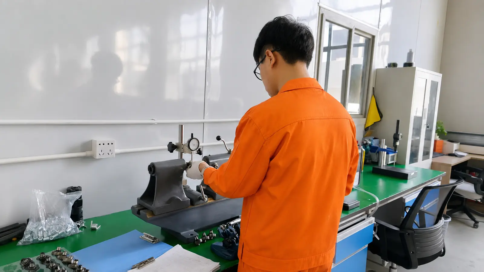
Machining capability for rotary-hammer accessories includes supported turning, profile milling and fixtures for parallel or individually held tools. The photographs identify the workpiece and setup so buyers can distinguish body machining from fluted-drill processing.
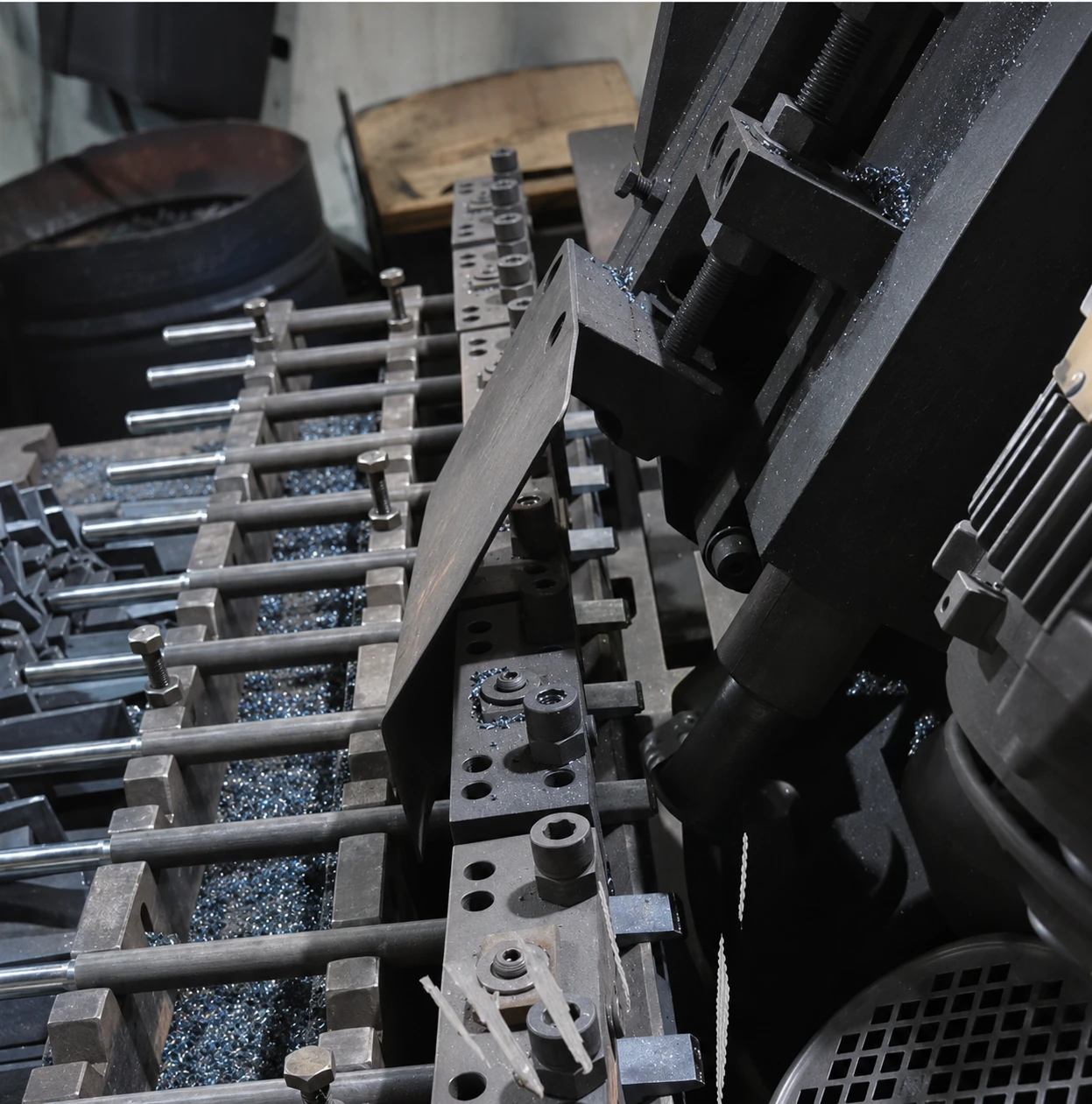
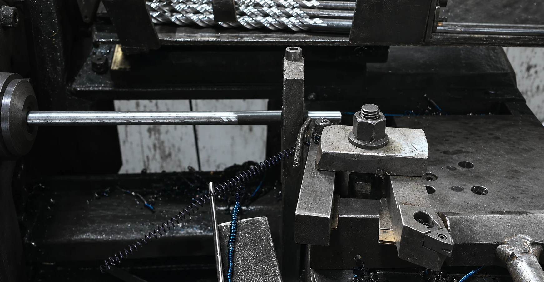
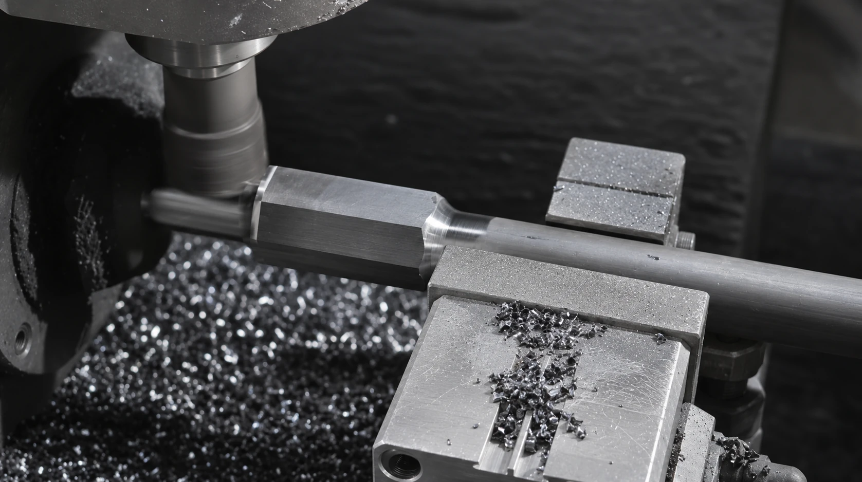
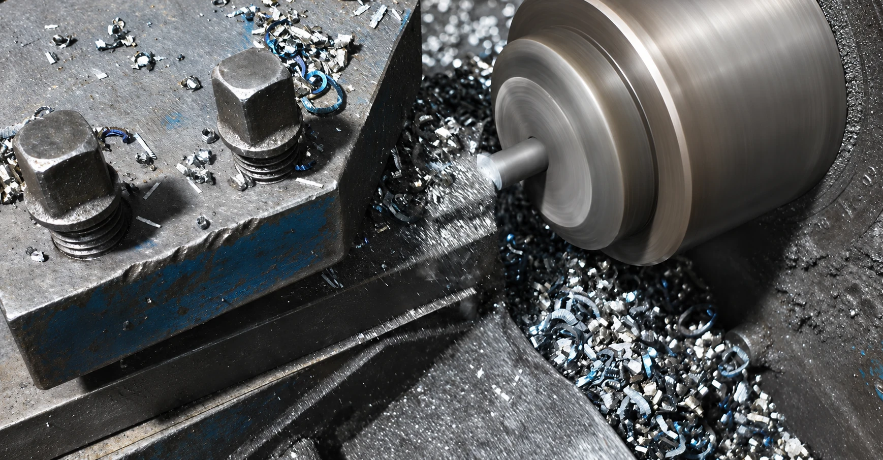
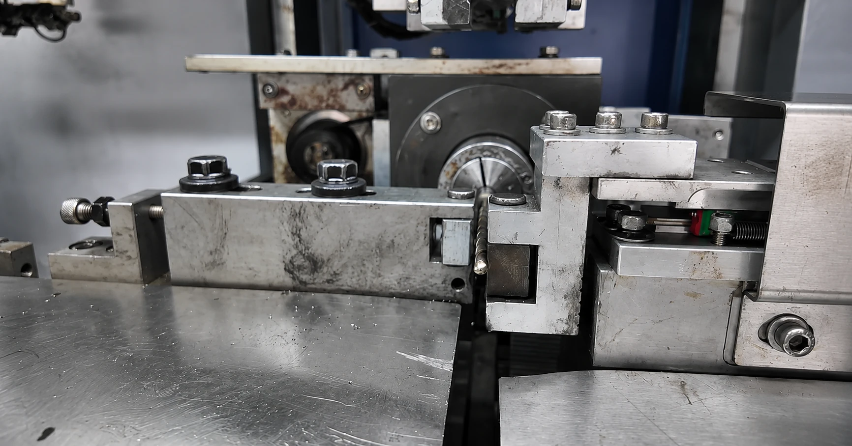
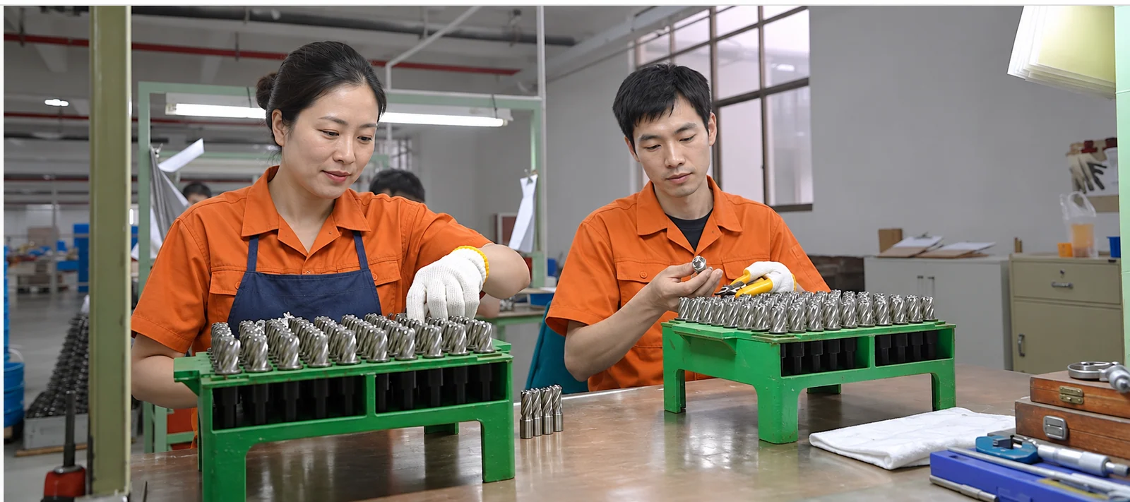
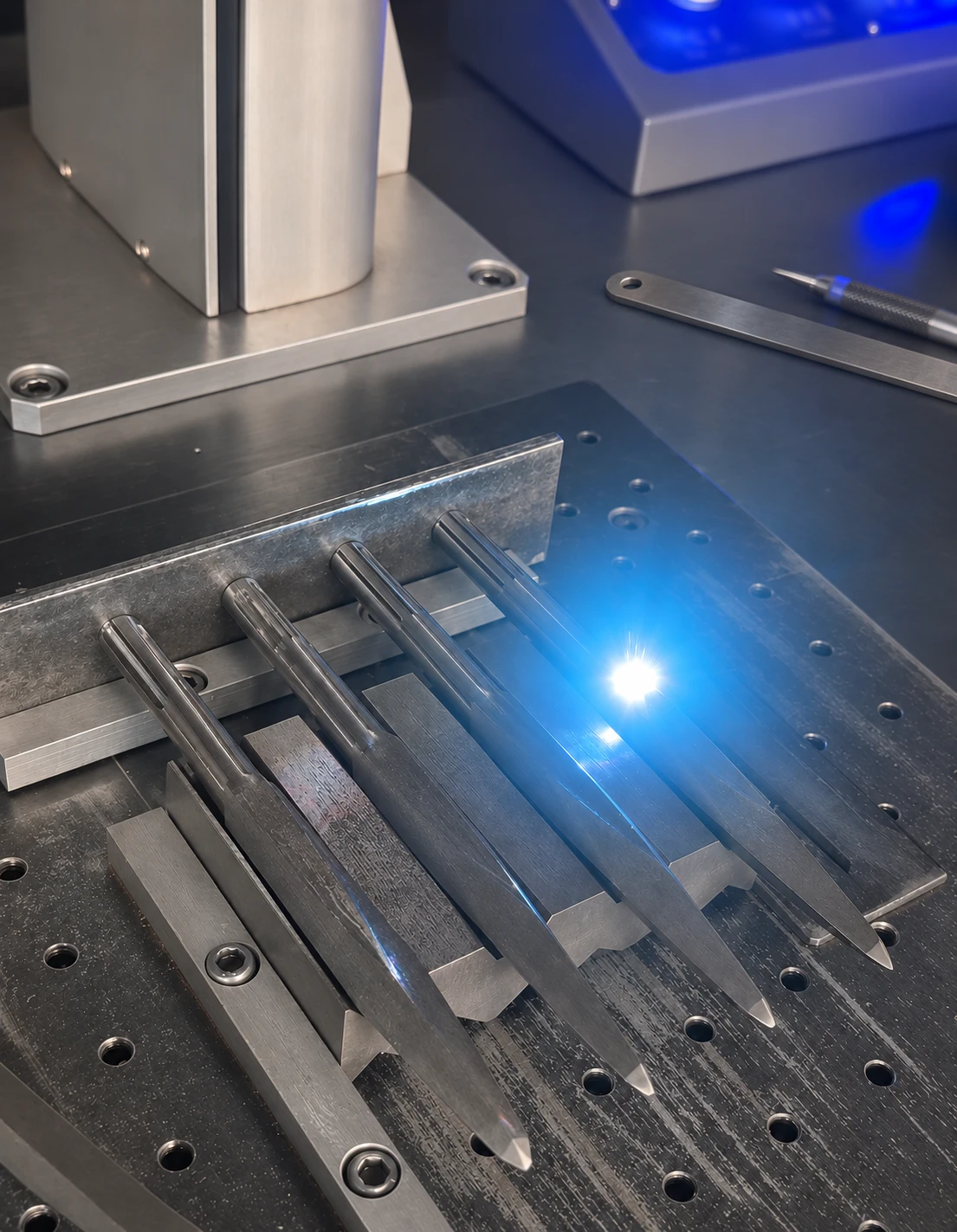
Finishing workstations address different working-end geometries across the factory range: pointed chisel tips, fluted drilling tools and batches of tool blanks. Keep the required product finish and working profile in the order description.
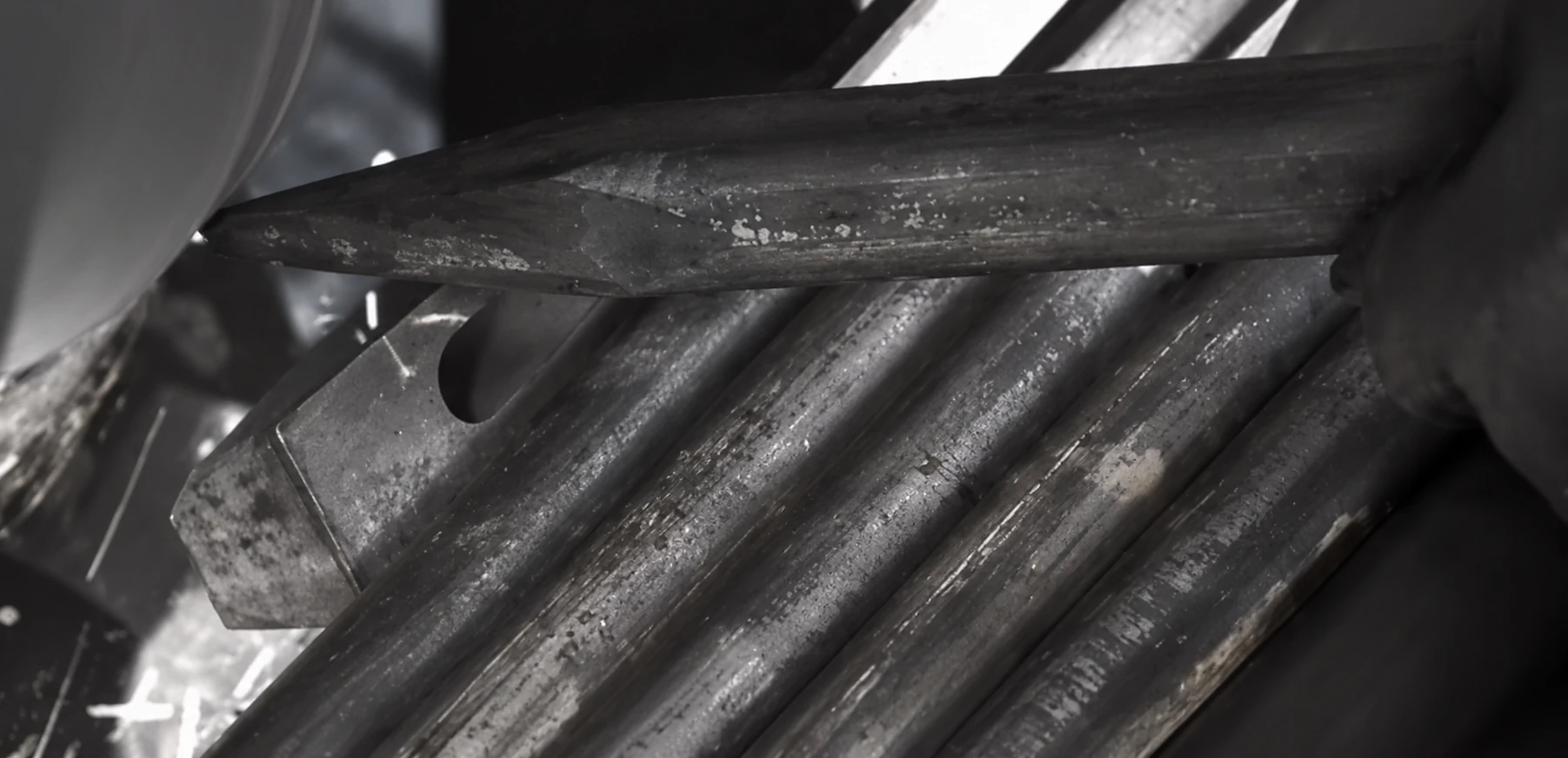
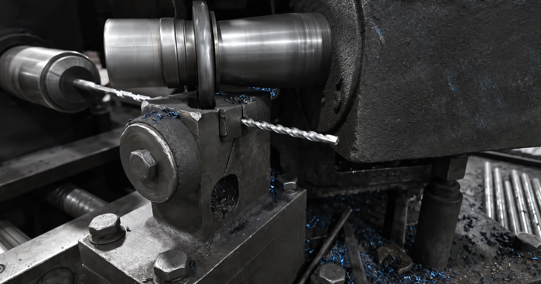
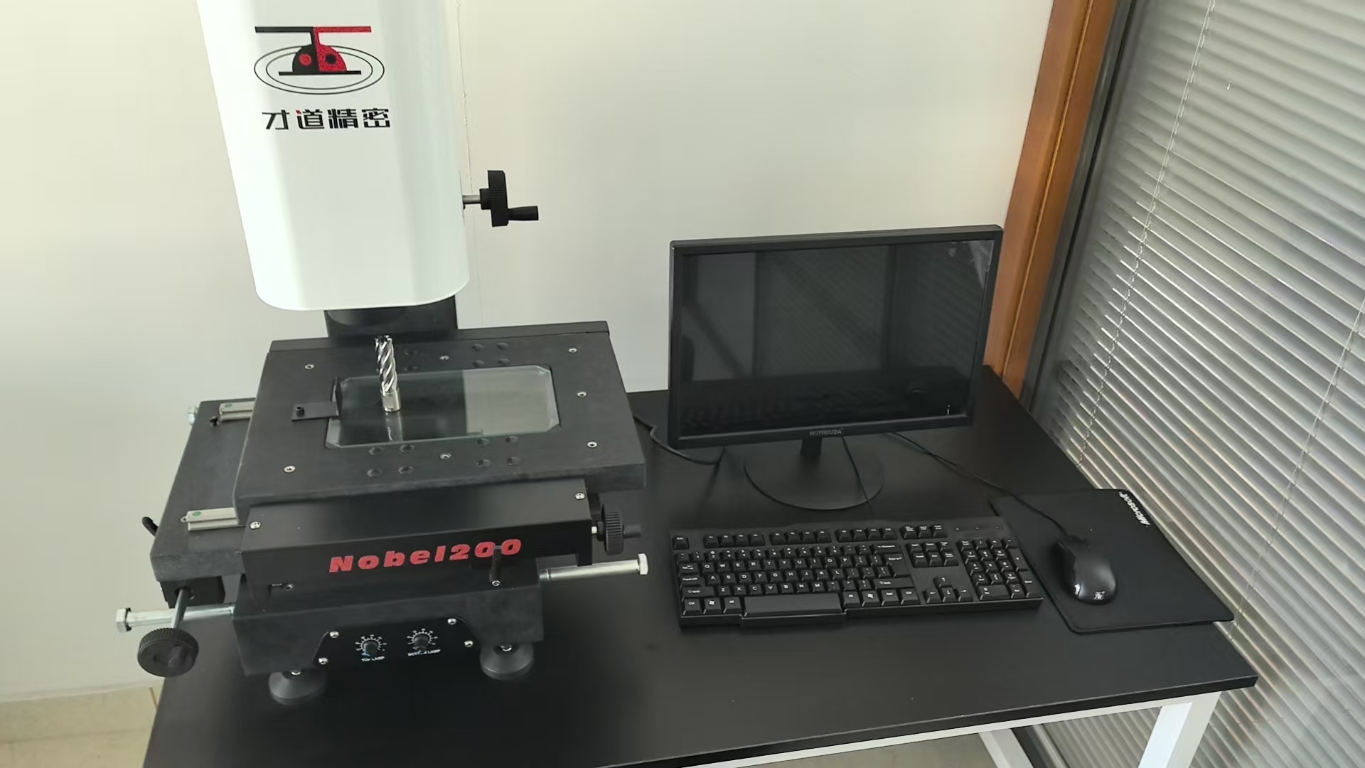
Our factory inspection workflow covers dimensions, geometry, hardness and visual consistency across SDS and masonry tool production. Inspection equipment and operator-led batch reviews support identification and acceptance across the wider cutting-accessory range.
For Tile Chisel purchasing, retain the selected holder system, body form, overall length, blade width and stated bend through sample and batch review. Connect the agreed inspection requirements with the buyer’s item code and pack identification.
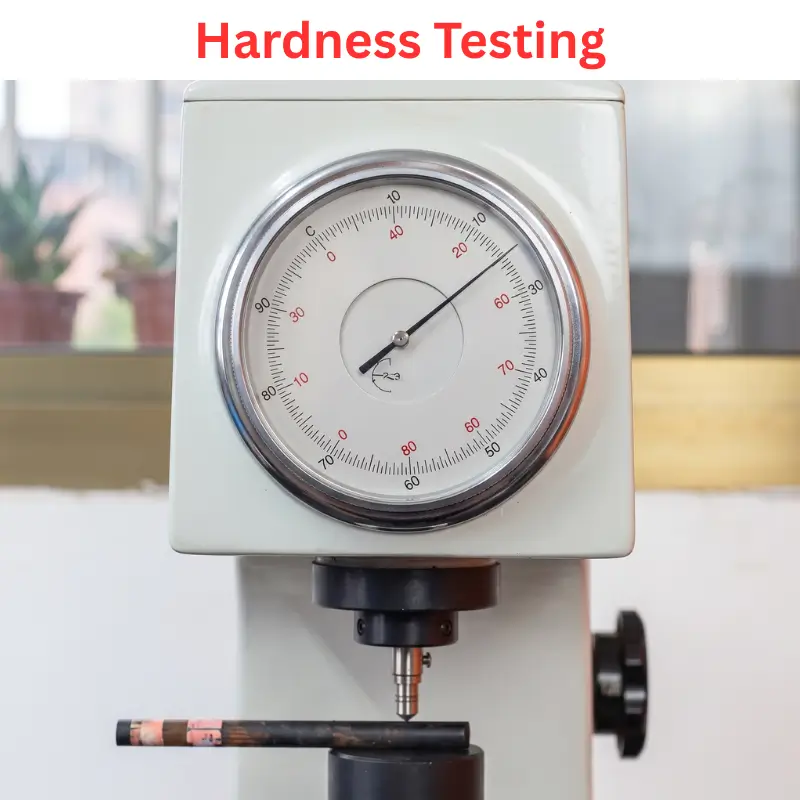
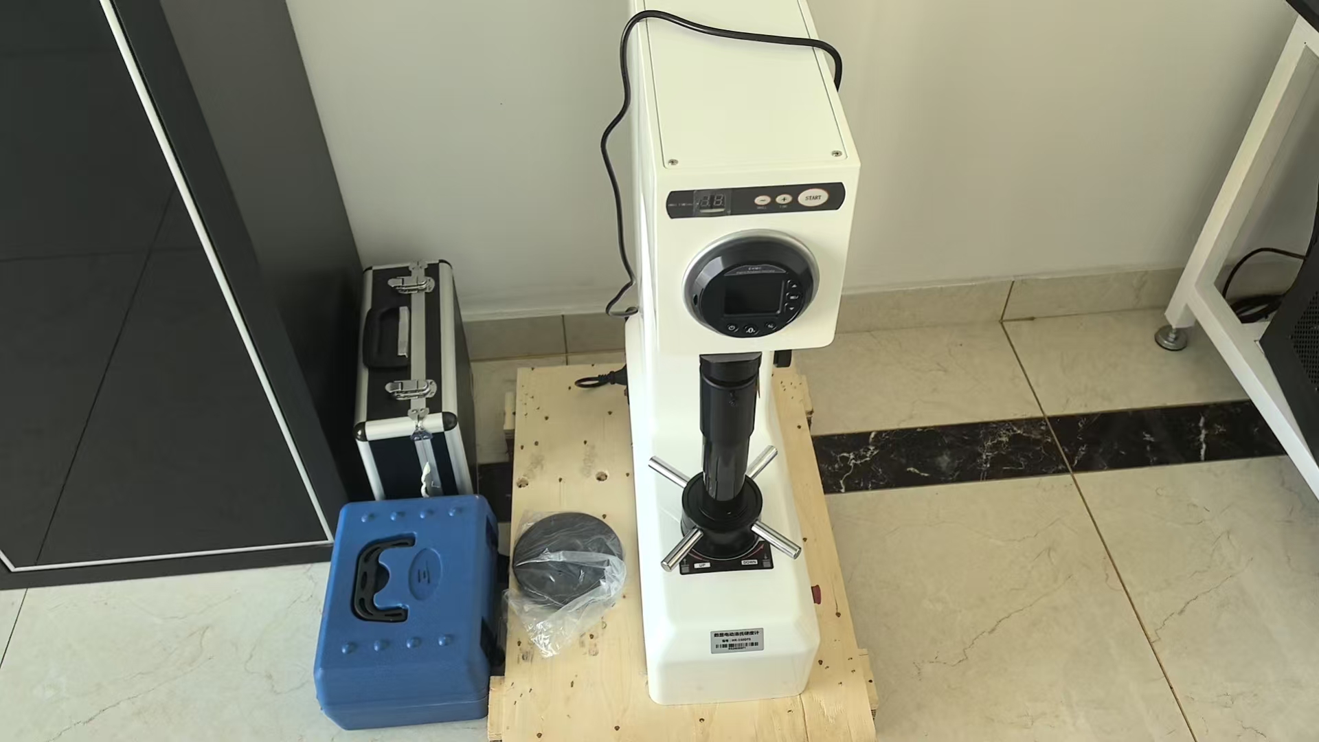
Hardness workstations, component measurement and manual batch inspection form complementary parts of the factory quality workflow. Numerical acceptance limits and any requested inspection records belong to the agreed item specification.
Keep one complete configuration and quantity per order line. Group SDS Plus and SDS Max separately. For the two 250 × 40 mm bent SDS Plus options, state the body form; for 75 mm tools, retain both the connection and the selected length.
For importers, begin with the holder systems already used in the destination market. Then separate customers who need narrow entry tools from those asking for broad tile-lifting contact. That gives an assortment a purchasing logic without assuming that all seven configurations need equal quantities. A common width should not hide a difference in working form or body.
Provide the buyer item reference, artwork and preferred marking content. Keep the connection, dimensions and specified bend legible in the branded item record. Describe product marking separately from the pack label so an artwork change does not alter the tool identity.
Describe bulk or individual presentation, tools per pack, edge protection and label language. For a blister, colour-box or mixed-pack brief, identify the exact configurations and quantities. Include barcode artwork and destination-market requirements in the same enquiry.
Reference the agreed product and pack description with your item code. Compare body, head transition, holder connection, length and width against that record. Keep configuration and packaging revisions separate, and retain quantities by item through sample review and repeat purchasing.
Record acceptance points against each purchased configuration. A dimensional review can identify overall length and blade width; a visual comparison can address body form, head transition and the specified bent profile. Check that the interface description on the item list agrees with the tool supplied. Keep these checks distinct from any machine-specific trial, because matching dimensions alone does not demonstrate performance in a particular tile system.
For mixed orders, compare item identification and quantities before combining the products into an assortment. Check that packaging protects the working edges and that labels distinguish the two holder systems. If the order uses a buyer’s item code, retain its association with the full configuration through sample review, packing instructions and repeat-order communication. These are purchasing and acceptance checkpoints, not claims of a certified test result or a published service-life figure.
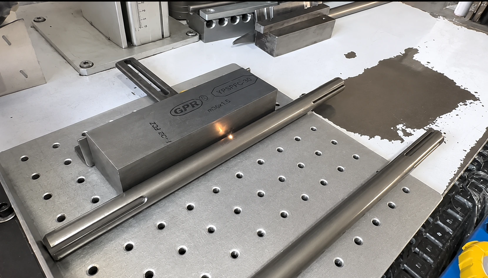
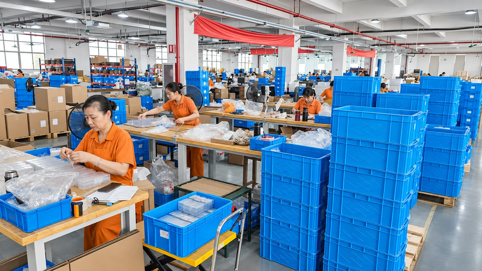
Marking fixtures, identified tool batches and factory packing workstations connect the product specification with the buyer’s presentation requirements. Provide artwork, item references, configuration quantities and packaging instructions together.
Select the machine connection first, then consider the available entry edge, the tile bed and any finishes that must remain. If the working position is uncertain, use the recommendation enquiry with the hammer model and a photograph of the removal area.
The machine must support the prescribed non-rotating chiselling mode as well as the correct SDS connection. Check its own insertion, retention and operating instructions; an SDS-labelled accessory does not add a chiselling mode to a drill.
Consider the space available for the entire working edge, particularly at boundaries and partly retained tiles. The available width must be chosen with the listed profile and length; a wider edge is not a guaranteed faster-removal option.
No. Only the five entries marked 15° carry that bend designation. The two separate tile forms have no angle listed; that omission does not mean a specified 0° profile.
The tile chisel is an integral tool. A replaceable-blade floor scraper also requires blade, holder and fastener identification when purchasing replacements or spare parts.
Compare clearance for the full hammer-and-chisel assembly. These two 75 mm SDS Plus choices have the same stated bend but different overall lengths; neither length alone establishes suitability for a particular tile bed.
No. The hexagonal-body 250 × 40 mm bent configuration uses SDS Plus. Include the body description in your enquiry to distinguish it from the round-body configuration with the same dimensions and bend.
No damage-free result is promised. Describe the substrate and adjacent finishes that must remain so the tool and approach can be considered for those constraints. Follow the machine instructions and assess the remaining surface after removal.
Add each required configuration to Message, then enter its quantity and pack requirement on that line. Include destination market and buyer item references. The existing message is retained when you add another row or change the connection filter.
List tools per pack, configuration mix, label language, barcode or artwork references and required edge protection. Keep the two holder systems distinguishable. Specify any changes from a repeat-order pack description.
Select one or more complete configurations above. Each is added to the existing Message once; your own wording stays in place. Enter quantities by item, packaging requirements and the intended machine or application. For a mixed order, keep each quantity attached to its configuration.