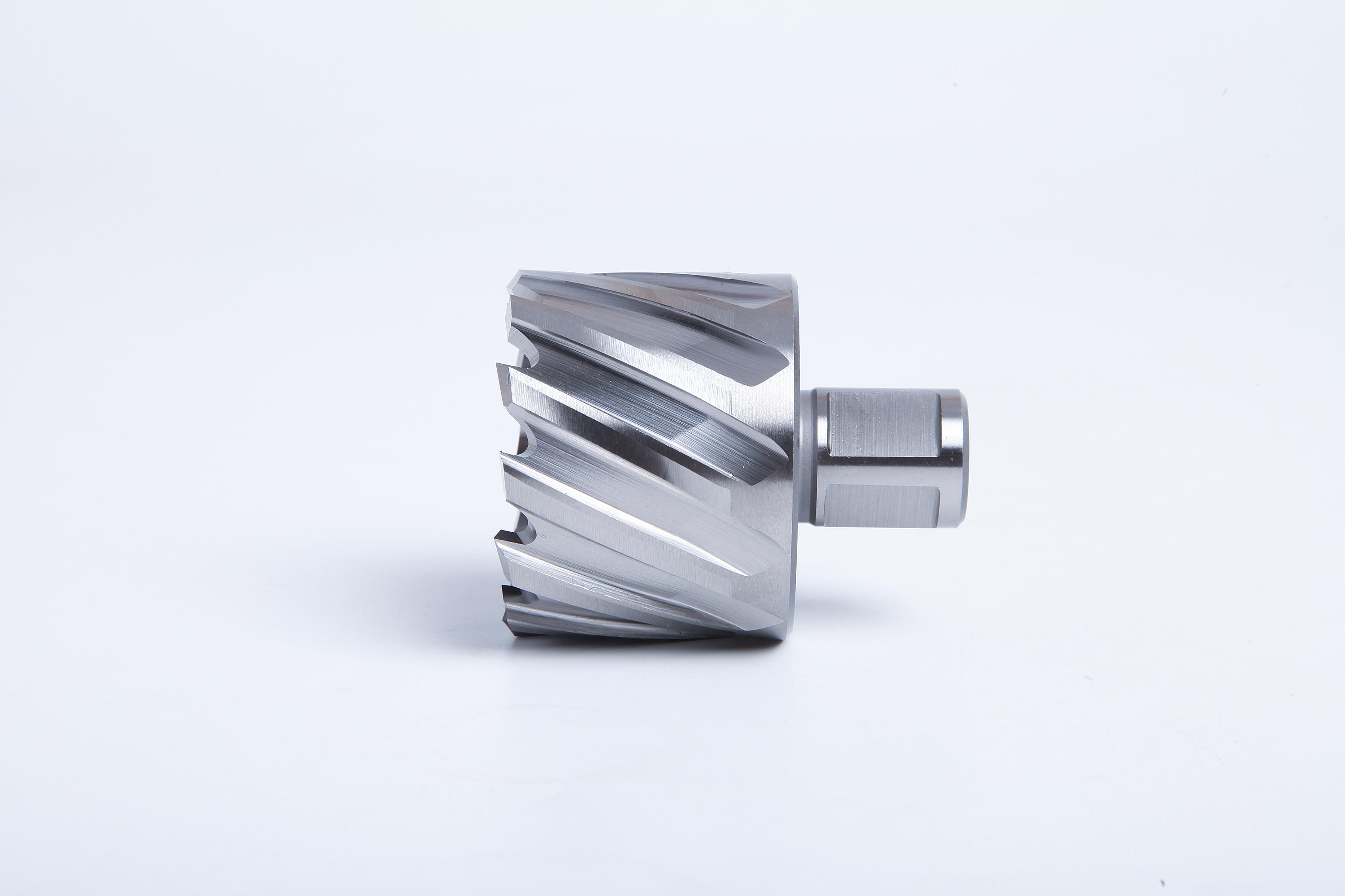
Annular cutters are not universally interchangeable. Many use a common Weldon connection, but a usable replacement must also match the holder, pilot pin, cutting depth, machine capacity and available travel. Start with the exact cutter and magnetic drill combination rather than a photograph or the word “universal.”
What Interchangeability Actually Requires
An annular cutter removes a ring of material and leaves a central slug. Its cutting diameter determines the nominal hole size. Its shank connects the cutter to an arbor or holder, which in turn connects to the machine. A pilot runs through the cutter in many conventional magnetic-drill systems.
These are connected parts of one assembly. A cutter that enters the holder has passed only the first compatibility check. It may still require a different pilot, project too far for the available space or exceed the machine's permitted diameter for that cutter construction.
Genuine interchangeability means that the replacement can be retained correctly and perform the intended operation within the machine and tool instructions. Common standardized interfaces make that possible across many products; they do not make every cutter suitable for every machine or job.
This is also why “universal shank” needs a more precise description. A product may be designed to work with several specified mounting systems, but the wording does not identify which systems, dimensions or limitations apply. Read the interface drawing and stated compatibility for that exact series.
What Is a Weldon Shank?
In annular-cutter catalogues, the common 3/4-inch Weldon connection uses a cylindrical shank with two clamping flats arranged at 90 degrees. The nominal diameter is 19.05 mm. A matching holder uses its specified retaining arrangement to engage those flats.
That figure describes the mounting end, not the diameter of the hole being cut. A range of different cutting diameters can share the same shank. Conversely, two cutters with the same cutting diameter can use different mounting systems.
“Weldon 19” or “19 mm Weldon” is often used as catalogue shorthand for this interface. Do not turn rounded wording into a workshop drawing. Where fit or replacement is in question, use the stated interface dimensions and the holder manufacturer's specification.
There are also larger Weldon mounting systems. A larger Weldon shank does not fit a 3/4-inch holder merely because both carry the Weldon name. Identify the actual connection before comparing the cutting tools attached to it.
For practical purchasing, the useful description is the complete interface plus the cutter size and usable depth. That removes the ambiguity in a line such as “Weldon cutter, same size as before,” especially where several drill models share one stores area.
Separate Hole Diameter, Shank Diameter and Cutting Depth
| Dimension | What It Describes | Common Ordering Error |
|---|---|---|
| Cutting diameter | Nominal hole produced by the teeth | Reading it as the shank size |
| Shank diameter and form | Mounting connection to the holder | Assuming equal cutting diameters mean equal fit |
| Rated cutting depth | Usable axial cutting capacity of the cutter | Substituting overall length |
| Overall cutter length | End-to-end tool dimension | Assuming all of it can enter the material |
| Assembled projection | Holder, adapter, cutter and pilot arrangement | Ignoring machine clearance and travel |
A description containing “3/4” is particularly easy to misunderstand. It might identify a 3/4-inch cutting diameter or a 3/4-inch Weldon shank. Write the unit and the role beside the value. The same discipline applies to another fractional cutting size: a 5/8-inch cutter is not automatically a tool with a 5/8-inch mounting connection.
For depth, start with the material thickness and the intended hole. The cutter must be suitable for the required usable cut. Overall length may include the shank and other non-cutting portions, so measuring the tool from end to end does not establish its rated depth.
Check the cut and the assembly separately. A cutter may have enough rated cutting depth but leave insufficient room to place the machine, position the pilot or retract and remove the slug. A dimensional match on paper must still work within the available space.
Compare Weldon With Quick-Change Systems
A Similar Cylindrical Shape Does Not Prove Fit
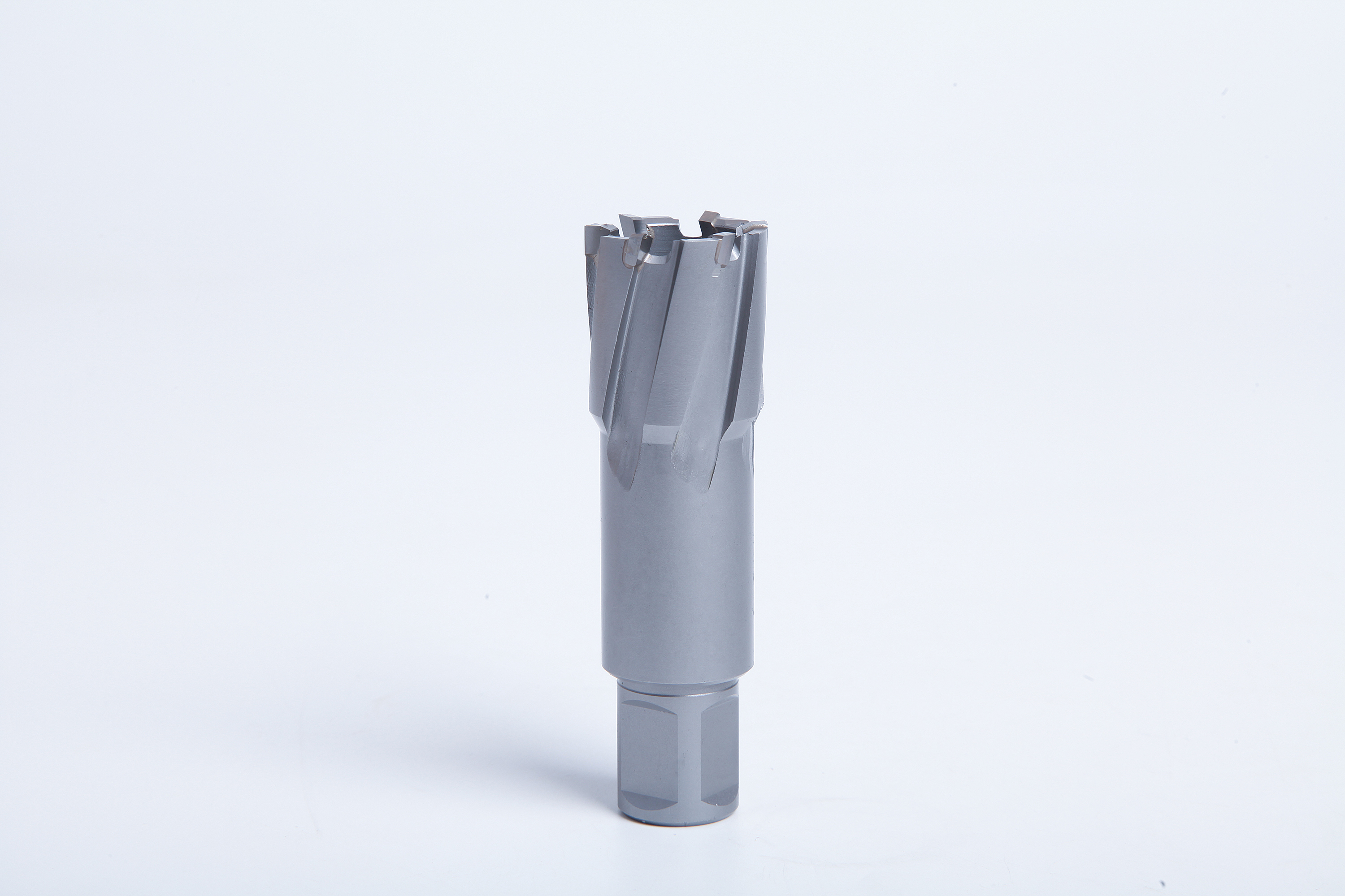
Different systems can look similar in a small product image. Weldon flats and a quick-change retention profile perform different mounting functions. The shape, seating position and retention components must belong to the intended system.
FEIN's conventional QuickIN annular-cutter connection, for example, is described as an 18 mm cylindrical shank with four circular recesses. That is a different interface from the 3/4-inch Weldon connection. This example explains why a visual resemblance cannot replace identification; it is not a claim that all quick-change systems share QuickIN dimensions.
Other manufacturers use their own named connections and adapters. Some are intended for particular compact drills. Keep their exact names in the compatibility record rather than replacing them with the generic phrase “quick change.”
Cross-Brand Use Can Be Valid
A properly specified common Weldon interface can allow cross-brand use. The sensible question is not whether the brand names match, but whether the cutter, holder and pilot combination meets the dimensional and operating requirements.
At the same time, a broad marketplace statement such as “fits all magnetic drills” leaves too many details unresolved. Identify the actual holder fitted to the drill; a machine may have different approved accessories or configurations. Confirm the complete assembly rather than rejecting cross-brand tooling automatically or accepting it without a check.
Match the Cutter to the Holder and Spindle
The cutter shank and the machine spindle are not necessarily the same connection. A magnetic drill may use a dedicated arbor, a removable cutter holder or another approved spindle arrangement. An adapter can sit between two of those components.
Trace the assembly from the machine outward: spindle connection, holder or adapter, cutter shank, then pilot. Each joint needs the correct seating and retention. This makes it easier to locate a mismatch instead of repeatedly changing the cutter.
For a screw-retained holder, follow its instructions for seating the shank and engaging the flats. Do not use a retaining screw to force a mismatched shank into position. For a quick-change holder, its locking mechanism must engage fully as designed. A tool that appears held while stationary may still be incorrectly seated.
Inspect the interfaces with the machine isolated from power. Burrs, chips, damage or the wrong retaining components can prevent correct seating. Correct the cause using the manufacturer's service guidance; grinding a flat, modifying a locking recess or substituting an improvised pin is not a compatibility solution.

Choose the Correct Pilot Pin
The pilot is a functional component, not just a pointed accessory supplied in the box. In common through-coolant magnetic-drill arrangements, it helps locate the hole, participates in the coolant system and assists slug ejection. Its exact role depends on the machine and cutter design.
A pilot pin is not a predrilled pilot hole. Conventional annular cutting generally does not require a smaller twist-drilled hole first: the cutter removes a ring, while its specified pilot locates the centre. Follow the exact system's starting procedure. Enlarging an existing hole or another special application may require a different pilot arrangement; do not improvise one.
A suitable pilot must match the cutter's internal arrangement and the holder assembly. Length, diameter, seating features and movement matter. Changing cutter depth or adding an adapter can change the pilot requirement even when the cutting diameter remains the same.
Do not select a pilot solely because it slides into the centre bore. It must operate through the required travel without becoming an unintended stop. Use the specified pilot reference or a confirmed compatible equivalent for the complete assembly.
Do not assume one cutting-depth family uses one pilot for every diameter. A manufacturer's range can divide pilot references by both diameter group and depth. Record the cutter series, cutting diameter and rated depth together when asking for a replacement pilot. A pin supplied with a previous kit is not evidence that it belongs with every cutter later added to the case.
If the pilot is missing, bent, stuck or no longer moving as intended, stop and inspect the arrangement before drilling. Forcing the feed is not a substitute for correcting it. Keep pilot references beside cutter and holder references when managing replacements, particularly where short and long cutting-depth families share a storage cabinet.
Check Stroke, Height and Slug-Ejection Space
Machine stroke describes available movement, while installed height and tool projection affect where that movement starts and ends. A compact low-profile drill can have a different usable tool envelope from an adjustable-height machine even when both accept a familiar shank.
Consider the complete sequence. The assembly must clear the workpiece for positioning, reach the starting point, complete the cut and retract sufficiently. The slug also needs an appropriate ejection path. Available stroke by itself does not prove that this sequence fits beneath an obstruction or inside a fabricated section.
An adapter adds another component and may change the installed length. That can remove useful clearance without changing the cutter's rated depth. Check the assembled dimensions rather than adding only the cutter and workpiece dimensions from separate catalogue pages.
For a trial assembly, follow the machine instructions with power isolated. Inspect travel and clearance without putting hands near the cutting teeth or an ejection path. Account for the real workpiece supports and fixtures: an unobstructed bench demonstration may not represent a hole close to a flange or another structural member.
Confirm Machine Capacity for the Selected Cutter
The machine must be rated for the cutter construction, diameter and operation. A hole capacity stated for one tool family should not automatically be transferred to another. HSS and carbide-tipped cutters may have different application guidance and preferred cutting conditions.
Physical fit does not create enough torque, an appropriate speed range or sufficient rigidity. This is particularly important when moving a large cutter from a more capable machine onto a compact drill. An adapter that joins the parts cannot increase the machine's permitted capacity.
Use the workpiece material and its condition when selecting the tool series. A cutter suitable for one steel is not automatically suitable for an unidentified hardened or abrasive component. Cutting data belongs to the selected tool and material combination, not simply to the word Weldon or to the fact that the machine has a magnetic base.
The base also needs a suitable mounting arrangement for the actual surface. Tool compatibility does not establish magnetic holding force on a thin, uneven, coated or non-magnetic workpiece. Follow the machine's mounting instructions, including required secondary restraint. Avoid treating a compatible cutter as approval for the entire installation.
Check the Coolant Route and the Type of Cut
A through-coolant arrangement needs a continuous working path through its intended components. A changed holder, adapter or pilot may affect that path. Do not assume that coolant reaching the outside of the assembly proves that it reaches the cutting region as intended.
Use the lubrication method allowed for the selected tool, machine and working position. General compatibility does not approve dry cutting, nor does it make liquid coolant appropriate in every orientation. Keep coolant away from electrical components and follow the machine's instructions.
The cut itself matters as well. A cutter intended for a single thickness is not automatically suitable for cutting through stacked plates. Stacked material can require a specific tooth geometry and a corresponding slug-release arrangement. Overlapping holes and interrupted surfaces are also separate application decisions, not ordinary compatibility checks passed by the shank.
Where the job changes from a simple through hole, describe that change before choosing a substitute. This prevents a correct replacement interface from hiding an incorrect cutting application.
Use Adapters for Defined Connections
An adapter is useful when it is designed and specified for the two connections involved. It is not a universal repair for an unknown mismatch. Check both sides of the adapter, its retention, pilot arrangement and the resulting assembly length.
A manufacturer may offer an adapter for one cutter family and particular drill models. That is evidence for the stated combination, not for every visually similar tool. Read the adapter's application limits together with the machine and cutter instructions.
For a workshop with several mounting systems, a clear compatibility chart is more useful than a box of unlabelled adapters. List the machine or holder, adapter reference where used, accepted cutter interface and pilot reference. Keep different cutter depths distinguishable if they require different pilots.
Do not adapt an annular cutter into a general hand drill simply because a chuck can hold an intervening arbor. The holder, machine, workholding and cutter all have to be approved for that method. Purpose-designed tooling for a drill press or other stationary machine is a separate system that requires its own instructions.
Troubleshoot Fit Before Starting the Cut
| Symptom | What to Check | Appropriate Response |
|---|---|---|
| Shank does not enter or seat | Connection type, dimensions, debris and damage | Identify the mismatch; do not force the tool |
| Retention does not engage fully | Seating depth, flats or locking profile, correct holder | Reassemble only to the holder instructions |
| Pilot bottoms out or sticks | Pilot reference, cutter depth, adapter and available movement | Stop and correct the specified combination |
| Tool fits but cannot reach the work | Installed height, projection, stroke and fixtures | Recheck the full assembly envelope |
| Coolant delivery changes after a swap | Holder path, pilot and adapter arrangement | Restore the approved delivery system |
| Cutter moves or chatters | Retention, machine mounting, cutter condition and application | Stop; find the cause before further cutting |
A compatibility check should happen before a production run, not after several damaged holes. If a replacement introduces a different holder or adapter, inspect the changed assembly rather than assuming that a previous machine approval still covers it.
Do not remove a stuck slug with the machine powered or put a hand in its ejection path. Use the cutter and machine manufacturer's removal procedure. A slug-ejection problem may involve tool condition, trapped chips, pilot movement or the cut itself; it is not proof that a different shank system is required.
Treat Wear as a Separate Compatibility Issue
A previously successful combination can stop seating or retaining correctly when a holder or shank is worn. A familiar part number does not rule out damage. If the cutter has developed movement, inspect both mating parts instead of assuming that a tighter retaining screw or a new pilot will correct it.
Likewise, do not transfer a cutter to a damaged holder to test whether the connection is compatible. Use the inspection and replacement criteria for the holder. Dimensional identification establishes which parts belong together; acceptable service condition establishes whether those particular parts can still be used.
Prepare a Replacement Request That Can Be Matched
A useful request identifies the magnetic-drill model and the holder actually fitted, then states hole diameter, required cutting depth, cutter construction, shank system and pilot reference. Add workpiece material and any access restriction. Photographs help identify the parts but should accompany dimensions and references.
For example, a request for the same hole diameter can still be incomplete if the replacement is deeper and needs another pilot. Likewise, “3/4 Weldon” alone does not tell the supplier whether 3/4 describes the hole or the connection. Label both fields explicitly.
If buying for a mixed machine fleet, organize cross-references by compatible assemblies. A purchasing list based only on cutting diameter makes it easy to issue the right-sized cutter with the wrong pilot or mounting system.
The annular cutter range is the starting point for cutter selection. Use the HSS versus TCT annular cutter guide when the remaining decision concerns cutting construction rather than mounting fit.
Frequently Asked Questions
Do All Annular Cutters Fit All Magnetic Drills?
No. Many share a common connection, but the machine's actual holder, permitted cutter capacity, available travel and pilot arrangement still need to match. Check the selected cutter diameter and usable depth as well as its shank. A physically retained tool can still be unsuitable for the intended cut or the space available.
What Does a 3/4-Inch Weldon Shank Mean?
It describes a common annular-cutter mounting interface with a nominal 19.05 mm cylindrical shank and two clamping flats at 90 degrees. It does not state the hole diameter. Different cutting sizes can share that connection. Keep the shank description separate from cutting diameter and compare it with the specification of the actual holder.
Is QuickIN the Same as Weldon?
No. FEIN's conventional QuickIN annular-cutter interface and the common 3/4-inch Weldon interface use different dimensions and retention features. An appropriate manufacturer-specified adapter may connect particular systems, but direct interchangeability should not be assumed. Other quick-change names also need their own identification; “quick change” is a function, not a complete mounting specification.
Can I Reuse the Same Pilot When Changing Cutters?
Sometimes, within the combinations specified for that pilot. Cutter depth, internal seat and the holder or adapter can change the required pilot length and movement. Matching the cutting diameter is not enough. Use the listed pilot reference for the assembly, and check that it is undamaged and operates correctly before starting the cut.
Can an Adapter Increase a Magnetic Drill's Capacity?
No. An adapter can connect compatible interfaces, but it cannot increase the machine's rated diameter, torque, speed range or rigidity. It can also change the installed length and pilot requirement. Check the machine, adapter and cutter limits together rather than treating successful mechanical connection as permission to use a larger or deeper cutter.
Can HSS and TCT Annular Cutters Be Swapped?
They can sometimes share a mounting interface, but that does not make them automatic substitutes. Confirm diameter, cutting depth, pilot, machine capacity and the operating data for the selected construction and material. A change from HSS to carbide-tipped cutting edges should be assessed as a tool-selection change as well as a mounting check.
Conclusion
Annular cutters can be interchangeable within clearly specified mounting systems, but there is no universal approval across all cutters, holders and magnetic drills. Identify the shank accurately, separate it from hole diameter, and check pilot, clearance, machine capacity and application together.
Send AXIMET the drill model, fitted holder, cutter diameter and depth, shank details and pilot reference to discuss a matching annular-cutter option.