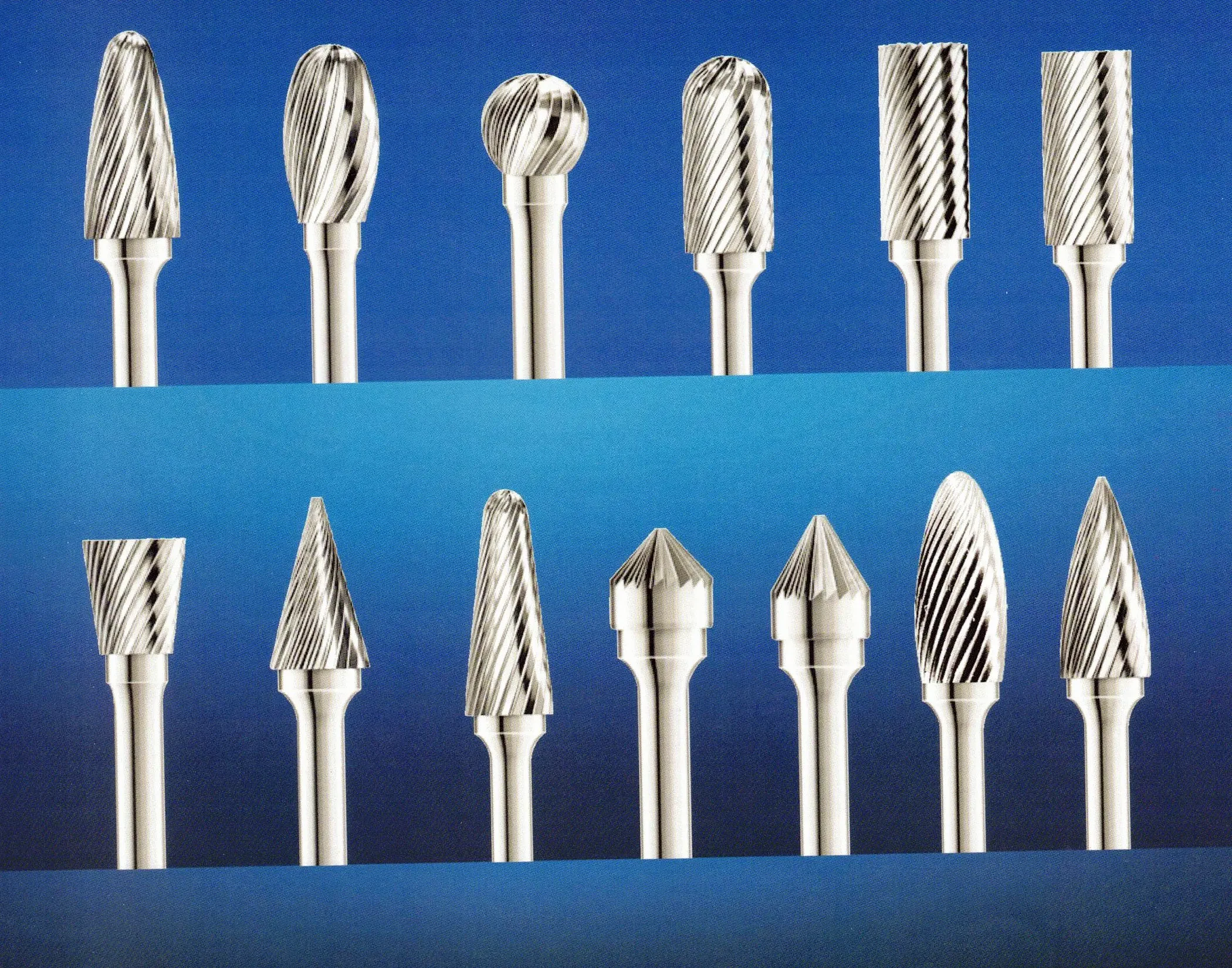
Choose a carbide burr by the surface it must reach: a cylinder for straight walls, a ball for concave areas, a tree for changing contours, and a cone for angled access. This carbide burr shape chart explains 13 common profiles and where each needs care.
A familiar-looking head can leave an unwanted hollow, round off a corner that must stay square, or foul an adjacent surface. The comparisons and examples below show how to select industrial metalworking burrs around those practical differences.
Carbide Burr Shape Chart at a Glance
Start with the workpiece outline, then compare the cutting head. The suggested applications below are starting points for selection; head dimensions, tooth geometry, material and access still determine whether a particular burr suits the job.
| Common Code | Head Profile | Useful Starting Application | Selection Boundary |
|---|---|---|---|
| SA | Cylinder, plain end | Side cutting along accessible straight walls and edges | Its plain end has no face-cutting teeth. |
| SB | Cylinder, end cut | Side cutting plus accessible end-face work | End cutting does not make it a drill or a general-purpose plunging tool. |
| SC | Cylinder, radius end | Straight sections that blend into a rounded transition | The rounded nose cannot preserve a sharp internal corner. |
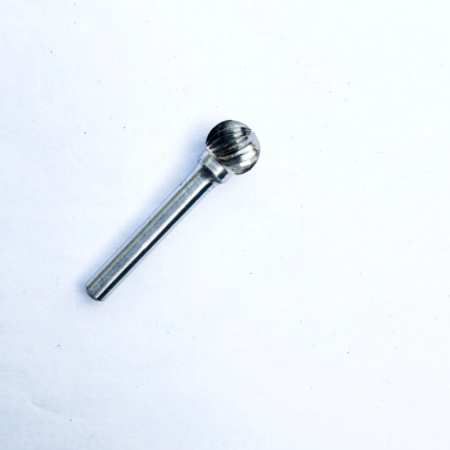
| SD | Ball | Local concave shaping and accessible curved recesses | A spherical head can leave a hollow on a surface intended to remain flat. |
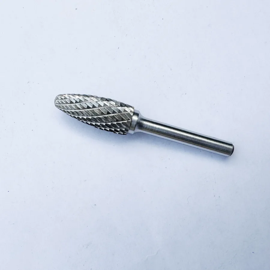
| SE | Oval or egg | Blending along broader curved surfaces | Its curved profile is a poor starting choice when a straight wall must be preserved. |
| SF | Tree, radius end | Curved contours with narrowing access | The rounded end still needs clearance around the working area. |
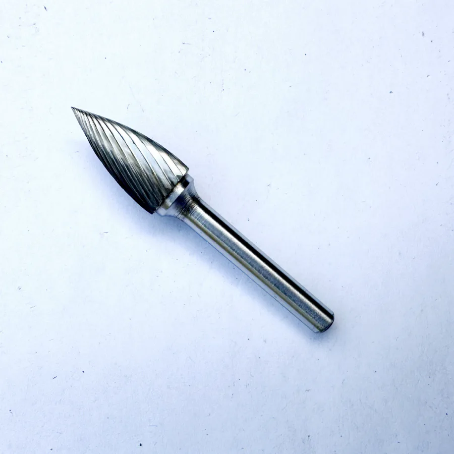
| SG | Tree, pointed end | Angled contours and more confined approaches | A pointed tip needs controlled contact; it is not a lever. |
| SH | Flame | Curved channels and elongated recessed contours | Check the complete head profile against the entrance and adjacent surfaces. |
| SJ | 60° cone | Accessible angled edges and local bevel work | The nominal included angle alone does not control the finished chamfer. |
| SK | 90° cone | Accessible angled edges and local bevel work | Handheld use does not produce a precision screw seat automatically. |
| SL | Taper, radius end | Tapered access with a rounded transition | Taper angles vary by model; inspect the drawing. |
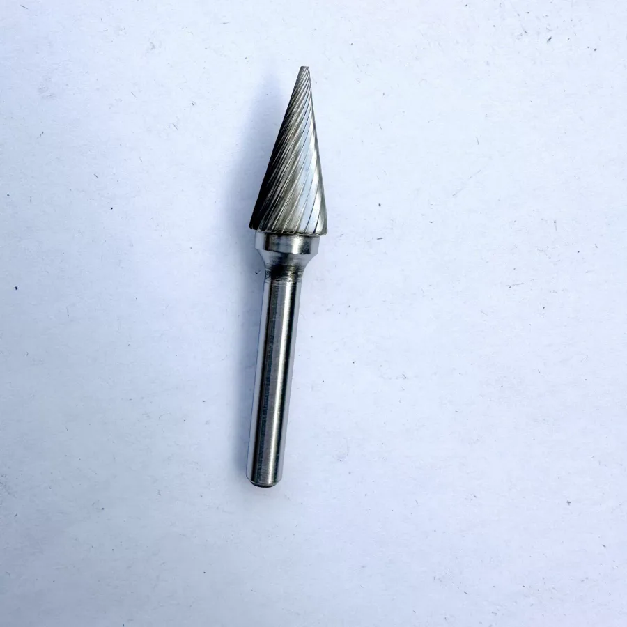
| SM | Pointed cone | Narrow angled features and accessible restricted contours | The point must not be forced into a closed corner. |
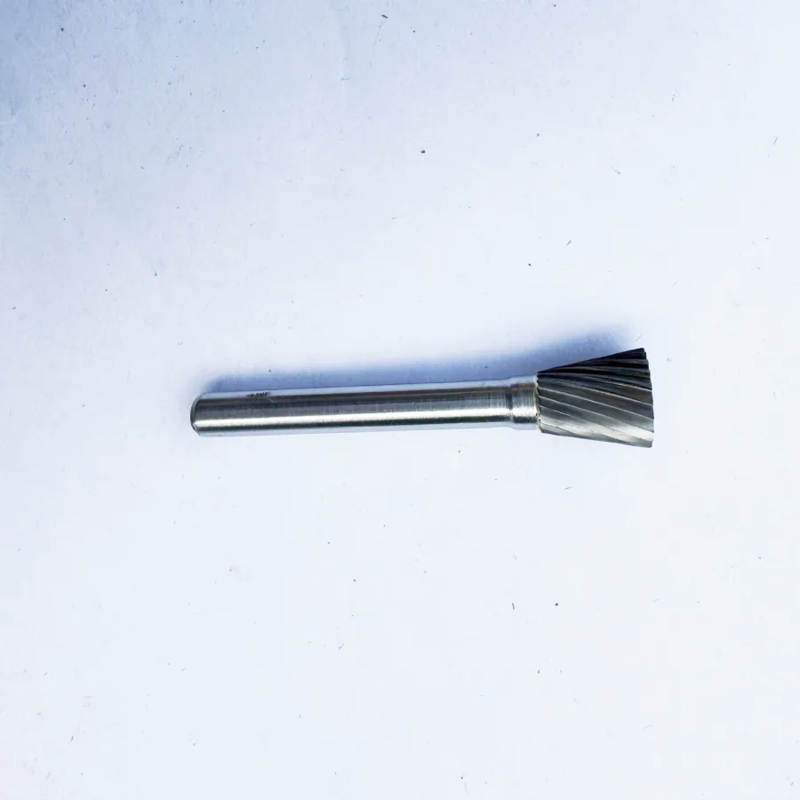
| SN | Inverted cone | Suitable reverse-side edges and features beneath a lip | The flared head must have a clear entry, working and withdrawal path. |
The head must fit while cutting, not only while entering the opening. A burr that passes through a hole can still be unsuitable once the grinder is tilted or the cutting head moves behind an edge.
What Do SA, SB and the Other Shape Codes Mean?
SA–SN are widely used catalog identifiers for industrial carbide burr profiles. They describe the head family, not its diameter, cutting length, shank size or tooth pattern. Several dimensions and cuts can exist within one family.
AXIMET uses Type A for the SA plain-end cylinder profile in this guide. This cross-reference describes the head shape only; it does not establish the same dimensions, tooth pattern or product specification. Other suppliers use different letter systems, so compare the actual profile and description. “Ball nose,” for example, may describe a cylinder with a rounded end, a tree with a rounded tip, or a tapered head. Those shapes approach the workpiece differently.
Keep shape selection separate from measurement. Use the carbide burr size chart when comparing head diameter, cutting length, shank fit and operating-speed references.
Choose the Contact Surface Before the Head Shape
Think about which part of the head should touch the metal and which nearby surfaces must remain untouched. Three questions narrow the selection quickly.
Does the Surface Need to Stay Straight or Curved?
A cylindrical side presents a straight profile along its length. A ball, oval or tree presents a curved profile. That difference matters when removing a small high spot from a wall: a ball can fit the opening yet encourage a localized hollow, while a cylinder can offer a more suitable contact outline.
For a rounded recess, the opposite applies. A square-ended cylinder may reach it, but its corner can interfere with the intended transition. Select a profile that approaches the required curve without forcing an unsuitable edge against the metal.
Is the Working Edge Visible and Accessible?
Check the approach from the operator’s actual position. A long cutting head, a wide grinder nose or an adjacent flange can prevent the intended angle even when the burr diameter appears small enough.
More reach does not solve every access problem. Sometimes the better choice is a smaller head, a different profile or a different tool arrangement. Avoid planning a cut that requires the shank or collet to rub against the component.
Is There Room to Move and Withdraw the Tool?
Leave room for a controlled pass and chip clearance. This is especially important around internal intersections and reverse edges. Do not select a head that becomes trapped when it reaches the cutting position. Reposition the component or choose another deburring method if controlled access is unavailable.
The Shape Differences That Most Often Cause Wrong Purchases
SA vs SB: The End Face Changes the Job
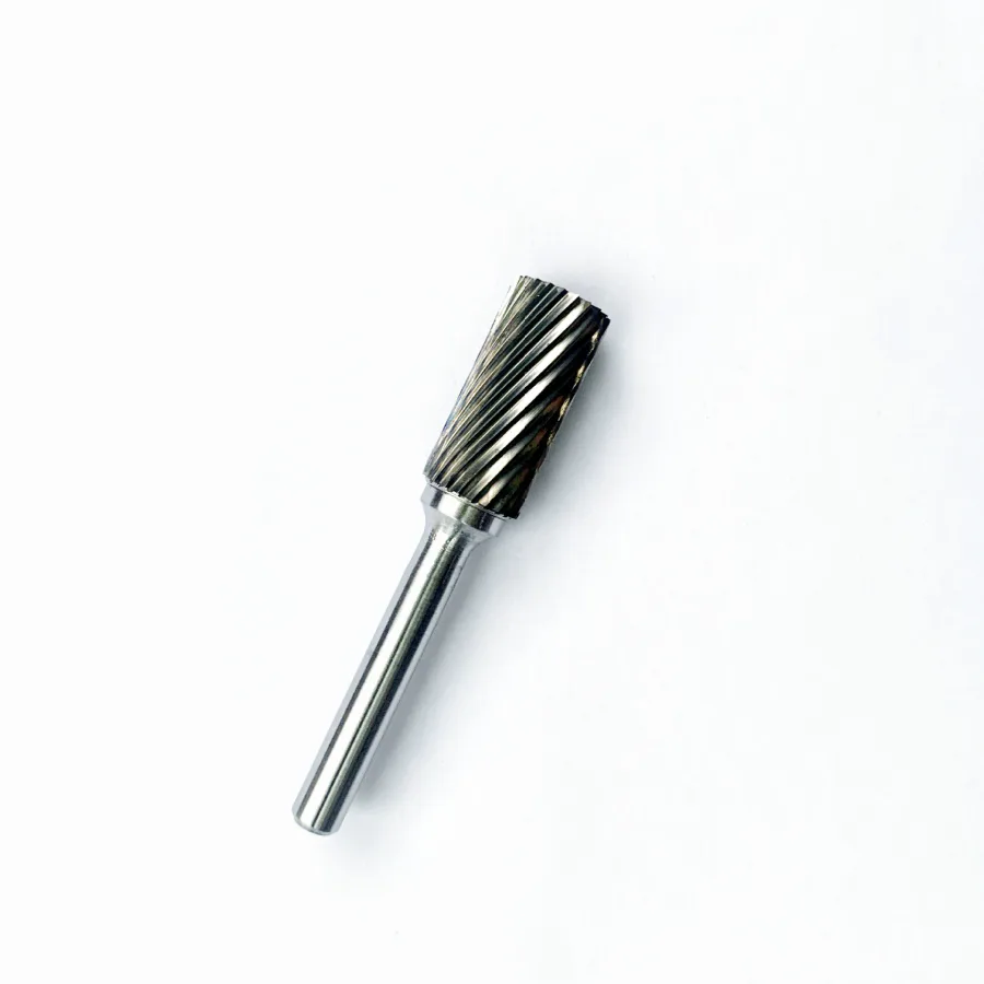
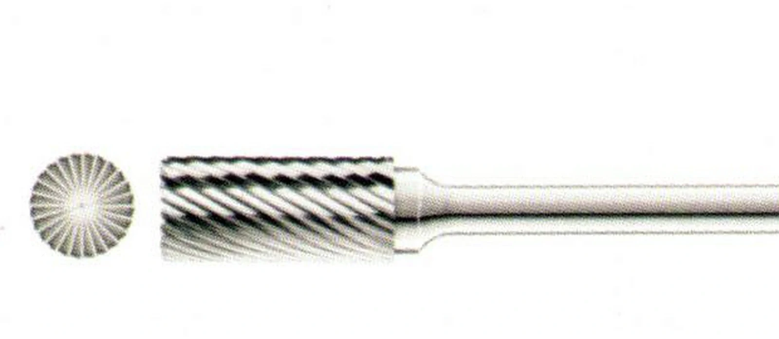
An SA cylinder cuts around its cylindrical surface and has a plain end. An SB cylinder also has cutting teeth on its end face. Their side views can look similar in a small product photograph, so inspect the end view.
Choose according to the contact the operation requires. If the work includes an accessible end-facing area, specifying only “cylindrical burr” leaves an important detail unresolved. For peripheral cutting beside a finished surface, inspect both the head outline and the available clearance. A plain end has no face-cutting teeth, but it can still rub or mark the workpiece; it is not a protective stop.
Neither head should be described as a substitute for a drill. End cutting alone does not establish suitable center-cutting geometry, chip evacuation or a controlled plunging process.
SC vs SD: A Rounded Cylinder Is Not a Ball
SC combines a cylindrical body with a rounded nose. SD has a ball-shaped cutting head. Choose SC when the operation includes a relatively straight section and a rounded transition. Consider SD when the useful contact is a localized concave area.
Imagine a recess with a straight side and a curved bottom. The SC profile can address both regions with different parts of its head. A ball offers a different contact pattern and requires care along the straight wall. Matching the nose radius alone misses this distinction.
SE vs SF: Broad Curves or a Narrowing Profile?
An oval SE has a fuller, continuously curved outline. The SF tree narrows towards a rounded tip. Both can suit curved contour work, but their clearance requirements differ.
When comparing them, trace the full head silhouette against the space around the feature. An oval may provide useful contact on an open curved surface. The narrowing tree may approach a contour where the fuller oval interferes with surrounding material. Do not assume two rounded heads will behave alike simply because both fit at their tips.
SF vs SG: Rounded Tip or Pointed Tip?
SF is the radius-end tree; SG is the pointed-end tree. The SG profile can approach narrower angled regions, while the SF’s rounded tip offers a different transition into the surrounding curve.
A pointed head is useful only where its contact can be controlled. It does not justify pressing into a closed corner or prying against an obstruction. If a rounded feature must remain rounded, begin by considering a radius-end profile that suits it, rather than asking the operator to keep a point away from the surface throughout every pass.
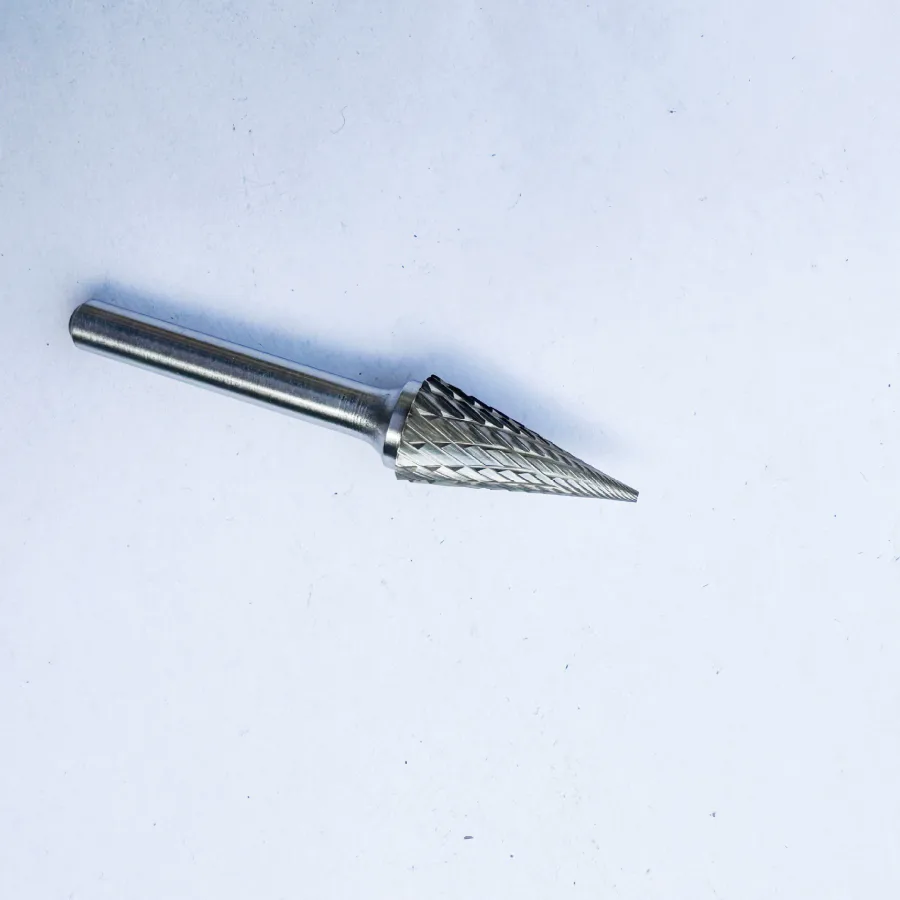
SH vs SL vs SM: Read the Side Profile
These tapered-looking heads are easy to confuse in a thumbnail. SH has an elongated flame outline with curved sides. SL has a taper terminating in a radius. SM comes to a point.
Compare the curvature, length and working diameter at the intended contact position. A flame may follow an elongated curved channel; a radius-end taper may fit a tapered approach; a pointed cone may reach a narrow angled region. These are geometry-based starting choices, not a ranking of which removes metal fastest.
SJ vs SK: Included Angle Is Not Grinder Position
The common SJ and SK families are designated 60° and 90° respectively. These are nominal included angles, measured between opposing sides of the cone in profile. They are not instructions to hold the die grinder at that angle to the workpiece.
A burr’s angle, its orientation, the contact position and the operator’s movement all affect the result. For a drawing-controlled countersink, screw seating surface or measured chamfer, use a suitable tool and controlled process. Do not choose a hand-guided cone burr solely because its catalog angle matches a drawing number.
SN: Plan the Reverse Edge Before the Cut
An inverted cone widens away from its shank. That reverse taper can approach suitable edges beneath a lip or on the far side of an opening.
Its widest section must still pass into and out of the feature. Check whether the head has end-cutting teeth if the proposed operation needs end contact; inverted-cone versions can differ. Never force the head behind an edge and rely on bending the shank to retrieve or guide it.
Four Practical Shape-Selection Examples
Removing Flash Beside a Straight Cast Wall
Suppose a casting has a raised line beside an otherwise straight wall. Start by considering a cylinder for peripheral contact, then check whether the burr also needs to work on an accessible end face. That separates an SA-type requirement from an SB-type requirement.
If the feature blends into a rounded base, assess an SC profile rather than carrying a square corner through the transition. The task may need more than one head; choosing a larger cylinder to finish everything in one pass can compromise access near the base.
Judge the result against the intended wall and edge shape, not just whether the visible flash has disappeared. Removing extra parent metal is not an improvement.
Blending a Curved Recess in an Aluminum Component
First compare ball, oval and radius-end tree profiles against the recess. A ball may suit a localized hollow; an oval may suit a more open curve; a radius-end tree may help where the approach narrows.
Then select tooth geometry intended for the alloy. The right outline with an unsuitable cut can still load with chips and perform poorly. Shape and material selection are separate decisions.
Also consider the next finishing stage. The burr should establish the required contour without leaving avoidable gouges for an abrasive tool to remove later. It should not be expected to deliver a polished surface simply because the head is rounded.
Working Near a Weld Toe or Adjacent Feature
For localized dressing where access is restricted, compare a tree, flame or radius-end taper. Consider how the side profile approaches the raised metal while staying clear of the adjacent component.
Choose the head that permits controlled contact from a workable position. A pointed tip may reach a confined spot, but a rounded profile may better suit an adjoining curved transition.
On structural or specification-controlled work, follow the welding and finishing requirements. A burr profile does not authorize removal of weld metal or changes to the joint geometry. If the required surface cannot be seen or inspected, reassess access before cutting.
Deburring the Far Side of an Opening
An inverted cone may be a candidate when the working edge lies behind an accessible opening. Compare the entry diameter, space behind the edge and available withdrawal movement before selecting it.
If the opening admits the head but leaves no room to present the correct cutting surface, the operation is unsuitable for that arrangement. A small ball or another tool may suit some accessible edges, but no profile removes the need for clearance and control.
Shape, Cut and Finish Are Separate Choices
A shape chart tells you where a head can contact the component. Tooth geometry determines how its cutting edges engage the material. The finished surface also depends on the tool condition, operating setup and technique.
Compare single-cut, double-cut and aluminum-cut burrs by their intended workpiece and operation. Do not buy the correct shape and then assume every available tooth pattern is interchangeable.
For an operation that continues from stock removal into blending or finishing, the next tool may be an abrasive accessory rather than another burr. The die grinder bits for metal guide explains that choice. For broader application examples, see what carbide burrs are used for.
How Wholesale Buyers Can Build a Useful Shape Range
Begin with the jobs your customers perform. A maintenance range for accessible edges and weld dressing has different priorities from a range for narrow casting passages. Buying one of every profile does not necessarily provide good coverage.
Group demand by contact geometry: straight walls, rounded recesses, narrowing contours and reverse edges. Then choose the head sizes and cuts needed within those groups. Two cylinders with different cuts or dimensions may serve distinct jobs; two nearly identical pointed profiles may add little practical coverage.
For a replacement or bulk inquiry, identify the head by name and profile, then provide the dimensions and job requirements below. If you only have a current tool, send clear side and end photographs with any measured dimensions. A worn head is useful identification evidence, but it does not establish the original geometry by itself.
| Include in the Request | Why It Matters |
|---|---|
| Shape name, code and side/end view | Separates similar profiles and end-cutting features. |
| Head diameter and cutting length | Defines the working envelope and contact area. |
| Exact shank diameter and required overall length | Identifies the machine interface and reach. |
| Workpiece material, operation and required contour | Gives context for the profile and tooth choice. |
| Tooth pattern and quantity by specification | Identifies the requested items in a mixed order. |
For a taper, end face or nose radius that affects the job, include the drawing. Evaluate samples on representative components for reach, unwanted contact and the contour left behind. Preserve that working specification when comparing replacements.
Frequently Asked Questions
What Are the Main Carbide Burr Shapes?
Common industrial families include plain and end-cut cylinders, radius-end cylinders, balls, ovals, rounded and pointed trees, flames, cones, radius-end tapers and inverted cones. SA–SN is a common identification system, but compare the actual profile when moving between supplier catalogs.
What Is the Difference Between SA and SB Burrs?
SA is a cylindrical burr without end cutting; SB adds cutting teeth to the end face. Both have cylindrical sides. Choose according to whether the operation requires peripheral contact alone or suitable end-face contact as well. SB is not automatically a drilling or plunge-cutting tool.
Is a Ball Burr the Same as a Ball-Nose Burr?
No. A ball burr normally means the SD spherical family. Ball-nose can describe the rounded tip of a cylinder, tree or cone. Those bodies have different contact and clearance characteristics. Specify the complete head description instead of ordering by “ball nose” alone.
Which Carbide Burr Shape Is Best for Tight Corners?
A pointed tree or cone may approach some narrow angled features, while a radius-end tree or taper may better match a curved transition. Compare the full working profile and surrounding clearance. A sharp point cannot compensate for an inaccessible cutting position or eliminate the risk of wedging.
Does a 90° Cone Burr Replace a Countersink?
Not for every operation. A 90° nominal head angle does not by itself produce a concentric, dimensionally controlled screw seat. Use the tool and process required by the drawing. A hand-guided cone burr can suit appropriate local deburring and bevel work without being a precision countersink replacement.
What Should I Specify When Ordering Carbide Burrs in Bulk?
Give the head shape, diameter, cutting length, exact shank diameter, tooth pattern and quantity for each item. Add the workpiece material and operation. If the end face, taper or nose radius affects access, include an end view or drawing. A current-tool photograph can help identify a replacement.
Conclusion
Choose the head profile around the contact you need and the surfaces you must preserve. Check its entry, working position and withdrawal path, then select the dimensions and cut for the material. A useful carbide burr range covers those jobs without relying on a single profile to do everything.
Explore the AXIMET carbide burr range by head profile. For a focused quotation, send AXIMET your requirements: the shape or clear side-and-end photos, dimensions, workpiece material, operation and quantities.

Melody
Trade Expert20-year foreign trade veteran and proud mother who believes in the power of continuous growth and a helping hand. By integrating the practical wisdom of AXIMET Tools into my daily workflow, I strive to make global trade more accessible and efficient for everyone I work with.
Discuss Your Requirements
Share the material, feature, tool setup, required result and quantities you are sourcing.